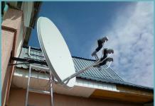
Cellular communications are used everywhere today. It is difficult to imagine a person who would not have a mobile phone. But, despite the widespread use of such communication, its quality is far from ideal. And not only various obstacles interfere with the passage of the signal, there are also other aspects, for example, living in a populated area with hilly terrain.
Mobile operators are trying to resolve these issues. But still, in the subway, parking lots, and even the lower floors of large shopping centers, you have to use a GSM repeater.
Sophisticated device for good communication
 A repeater is called differently - a repeater or an amplifier, but this does not change its essence. It is designed to improve the quality of the signal transmitted and received by a mobile phone and is a device that only works in conjunction with two antennas.
They are most often used to improve the quality of communication in populated areas with a weak or poor signal. In the first case, an external antenna allows you to achieve good results. In the second - a service one, located in the visibility zone of subscribers.
However, it should be taken into account that GSM signal repeaters are usually capable of operating only on one of the available communication bands.
We watch the video, the scope of use of the devices:
Another advantage of using such equipment is the ability to reduce the level of electromagnetic radiation from the devices. This allows you to reduce the negative impact on health and significantly increase the period of uninterrupted operation without recharging. The use of repeaters on airplanes makes it possible to reduce interference.
Amplifier operating principle
 In order to understand how the device functions, let’s look at its structure. Typically the kit includes:
- Antennas;
- Wires;
- Repeater.
The device itself receives radio waves at its location and redirects them to another area; in addition, it is a cellular amplifier.
The operating principle of such a device is to establish a connection between antennas with the possibility of changing the signal shape.
Having received reinforcement, he returns to the base of the mobile operator. However, for the GSM 3G repeater to work properly, you need good electromagnetic isolation between the two antennas. This will avoid the self-excitation effect, which leads to jamming of the signals of all nearby subscribers. This effect is achieved by separating devices over a long distance.
Let's watch the video, the kit and how it works:
Many models of these devices have a self-excitation protection system, and simpler samples signal the need for antenna spacing using indicator lights.
Types of repeaters, their features
The division of GSM signal repeaters into classes is carried out according to various criteria. Based on their characteristic features, the areas of use are divided into the following types:
- Subscription;
- Strip;
- Optical;
- Duct.
When solving complex problems, it is possible to use several different types of devices simultaneously. This must be taken into account when deciding which GSM repeater to choose.
In addition, there are differences in:
- Coverage area
- Power;
- Signal gain;
- Cellular standard.
Modern repeater models are capable of providing a coverage area from 50 to 300 m². The same goes for power. Devices on the market are represented by models in which this indicator ranges from 40 to 100 mW. Naturally, the effectiveness of using such devices also differs significantly.
The gain shows how much the power at the antenna input should be increased when replacing it with an omnidirectional one. It is one of the most important parameters that are taken into account when choosing a specific model and can range from 40 to 90 dB.
The cellular communication standard and frequency range of GSM repeaters of various modifications also differ significantly. The following devices are distinguished:
- CDMA 450 (3G);
- UMTS (3G);
- GSM 1800 900 (2G).
However, not only the listed characteristics make differences in GSM signal repeaters. These devices differ in other parameters:
- Bandwidth;
- Operating conditions;
- Method of application;
- Reliability and quality.
The quality of cellular communication depends on the choice of repeater
A wide range of repeaters on the market allows everyone to choose the necessary model. The cost of such equipment ranges from 10 to several 100 thousand rubles. However, when deciding how to choose a repeater, keep in mind that a cheap device cannot cover more than 200 m² of area. This means that it can only be used in small rooms. Expensive models are capable of covering much larger areas and are intended for use in industrial premises.
Since the cellular communications amplification system consists of several components, all of them must be selected in accordance with the required coverage area. Only with a successful combination can high quality coatings be achieved.
Best models
The use of these devices is not yet widely used and this is most often due to the ignorance of users about the advantages of the device. But a GSM repeater installed in an apartment will not only expand the coverage area, but also save the device’s charge and minimize harmful radiation.
Watch a video about the Picocell 900 SXB model:
Among the models that are in greatest demand, the following devices are worth noting. The Picocell 900 SXB model for a mobile phone belongs to the broadband cellular amplifiers of the 900 standard. It is used to improve the quality of calls from almost any mobile operator. The only condition is a sufficient signal level at the location where the external antenna is supposed to be installed.
Most often, such devices are used in small offices or residential premises. They are capable of providing a coverage area of up to 150 m². Installation of the repeater is allowed only in a heated room. It is small in size and weight, and also has low energy consumption and is capable of serving up to 15 subscribers simultaneously.
The repeater is easy to install and has the ability to adjust the gain. Its use allows you to access 2G mobile Internet.
 Another model is the Telestone TS GSM 1800 amplifier. It is designed for use in areas of very weak and poor signal and is designed for installation in large areas.
The operation of the active system created on the basis of this device is to receive a signal from the station using an external antenna. It is then amplified and distributed to users.
The principle of transmitting a signal in the other direction is similar - from the telephone to the station. The Telestone TS GSM 1800 repeater is usually used in premises with large areas: from private houses to underground parking lots and bunkers. It is equipped with status indicators, built-in signal level control and has self-excitation protection.
How to set up a GSM repeater yourself
The purchase of a device presupposes its further use. However, to use the repeater, you need not only to perform installation work, but also to configure the device correctly. The first thing you have to make sure is that there is no damage to the body of the device and its correct location away from the heating equipment.
Next we move on to connecting the cables. How to do this correctly is indicated on the front side of the device. To avoid the possibility of burning the repeater, you need to check the voltage before connecting. Only after this can you proceed to connecting the radio unit to the power adapter. If all operations were performed correctly, the green indicator on the panel will light up.
When setting up the equipment, you must not carry out any work with the connectors while the repeater is turned on. This may cause equipment damage. This means that the GSM repeater will need to be repaired. To ensure maximum coverage area, you need to change the gain.
Experts recommend choosing a value within 15 dB. When making adjustments, pay attention to the indicator light; if it turns red, it means you need to reduce the gain. To do this, rotate counterclockwise. If this does not lead to the light changing to green, then you will have to change the place where the antennas are located: internal and external.
After all of the above procedures have been completed, you can turn on the telephone and check the operation of the repeater. At the same time, do not forget to check the service area; if it is small, you will have to install additional antennas. That's all you need to do to configure and install the GSM repeater.
The history of transistors begins in the mid-20th century, when in 1956 three American physicists - D. Bardeen, W. Brattain, W. Shockley - were awarded the Nobel Prize for their research into semiconductors and the discovery of the transistor effect.
It is sometimes difficult for a radio engineer starting work in his field to understand electronic circuits and the purpose of certain of its components. For this, there are certain developments - already invented circuits for connecting transistors and other elements with certain properties, from which various devices can be composed. One of these “building blocks” in the building of electronic circuits is the emitter follower on a transistor.
Transistor connection diagrams
There are three types of inclusion of bipolar transistors - with a common base (CB), with a common emitter (CE) and a common collector (CC).
The most common connection is (OE), as it gives a large gain in voltage and current. One of the features of this connection is the inversion of the input voltage by 180 0. The disadvantage of the connection is the small input (hundreds of Ohms) and large output (tens of kOhms) resistance.
When an input voltage is applied, the transistor opens and current flows through the base to the emitter, while the collector current increases. The emitter current is summed from the base current and collector current: I E = I B + I K
In the collector circuit, across the resistor, a voltage appears that is much greater than the input signal, which leads to an increase in the output voltage, and accordingly, the current.
Turning on the transistor according to the (OB) circuit gives voltage gain and allows you to work with a wider frequency range than the circuit with (OE), therefore it is often used on antenna amplifiers. This circuit makes full use of the transistor's ability to amplify high-frequency signals (frequency characteristics). The higher the frequency of the amplified signal, the lower the voltage gain. This stage has low input and output resistance.

Turning on the transistor with (OK) gives current amplification and is often used as an adapter between a high-resistance power source and a low-resistance load. Also, this inclusion can be used when matching various cascade circuits; it does not change the polarity of the input signal.

General concepts about repeater
An emitter follower is a current signal amplifier in which the transistor is switched on according to the circuit (OK). The voltage gain of the signal is almost equal to unity, the emitter voltage is equal to the input signal, so the circuit is called an emitter follower. We will consider the operating principle of the device below.
Despite the fact that the emitter follower has a voltage transfer coefficient of unity, it can be classified as an amplifier, since it gives amplification in current, and therefore in power: I E = (β +1) x I B, where I E - emitter current, AND B - base current.
With low resistance, the collector of the transistor is connected to the common bus, and the resistor from which the output voltage is removed is connected to the emitter circuit. The input and output are connected to external circuits using capacitors C 1 and C 2. With a small voltage increase factor, the current increase factor reaches its peak in the short-circuit mode of the output terminals.
Operating principle
The load of the cascade repeater circuit is the emitter resistor R E. The input signal arrives through the first capacitor C 1, and the output signal is removed through the second capacitor C 2.
The emitter voltage follower has a very low input resistance and a large output resistance. With alternating current, when a half-wave of positive alternating voltage passes through a p-p-n transistor, it opens more strongly and the current increases; with a negative half-wave, the opposite is true. As a result, the output AC voltage has the same phase as the input voltage and is the feedback voltage. The output voltage is directed towards the input voltage and is connected in series, so the emitter follower uses serial negative feedback. The output voltage is less than the input voltage by an insignificant amount (base - emitter voltage is about 0.6 V).
How to calculate a circuit

The initial data to make the calculation of the emitter follower are the collector current (IK) and the supply voltage (U VX):
- The emitter voltage (U E) must correspond to: V E = 0.5 x V VX (to ensure maximum swing for the output voltage).
- Now you need to calculate the resistance of the resistor on the emitter: R E = Y E /I K.
- The resistance of the resistor divider is calculated: P 1 -P 2 (we select the resistance so that the current on the divider is approximately 10 times less than the base current): I D = 0.1 x I K / β, where β is the current gain transistor. Resistance P 1 + P 2 = U VX / I D.
- We calculate the base voltage relative to the ground: V B = V E + 0.7.
Distinctive features
The emitter follower has an interesting feature - the collector current depends only on the load resistance and input voltage, and the transistor parameters do not play a significant role. Such circuits are considered to have 100 percent voltage feedback. You don't have to worry about burning the transistor by supplying power to the base without a limiting resistor.
The operation of the emitter follower is based on a high input impedance, which allows you to connect a signal source with a high complex impedance to it (for example, a pickup in a radio). Amplifier
Very often, an emitter follower is used as a power amplifier in the output stages of amplifiers. The main task of such nodes is to transfer a certain power to the load. The most important parameter that is set in amplifier power calculations is the power gain , distortion of signal transmission and efficiency (its increase is necessary due to the consumption of most of the power of the power supply by the output amplifier) . Voltage gain is not a major parameter and usually approaches unity.
There are several ways of operating such an amplifier stage, depending on the location of the operating point on the characteristics graph and, accordingly, with different efficiency and characteristics of the output signal.
Operating modes
In the considered cases of operation of the emitter follower, the collector junction will be reverse biased and the operating mode will depend on the emitter junction:
- In the first case, the emitter junction is shifted in such a way that the transistor does not stably go into saturation mode and the repeater operates on the straight section of the transfer characteristic graph (voltages V K and V E are the same). The maximum output voltage is less than the input voltage. The efficiency is equal to the ratio of the power supplied to the load to the power from the power source, and reaches a maximum (25%) at the highest amplitude of the output voltage. To avoid mismatch between the output and input signals, the amplitude of the output voltage has to be reduced, as a result, the efficiency also decreases. The low efficiency in this operating mode of the repeater is due to the independence of the current passing through the transistor from the supply voltage and the power consumed from the power source is a constant value. In the absence of an input signal, the power dissipated by the transistor is greatest. Therefore, in this mode, the emitter follower is not used as a power amplifier, but rather as a low-distortion signal transmitter.
- Another operating mode of the amplifier stage, in which the bias of the emitter junction brings the operating point of the transistor to the boundary of the turn-off region. If we accept the emitter voltage (U E = 0) and there is no input signal, the emitter junction is reverse biased and the transistor is in the off state. As a result, power consumption is reduced. When a positive half-wave passes from the power source, the transistor is unlocked (the emitter junction opens), and the negative half-wave closes it (there is no output signal). The second case of operation of the amplifier stage solves the problem of increasing the efficiency of the amplifier, because there is no current on the transistor if there is no supply voltage. But there is a drawback - strong distortion of the output signal.
Push-pull circuit
A push-pull emitter follower allows for current amplification in the positive and negative ranges. To obtain a bipolar output signal, you can use a complementary emitter follower. In principle, a push-pull circuit consists of two repeaters, each of which amplifies the signal in the positive or negative half-wave. The circuit consists of two types of bipolar transistors (with p-p-p and p-p-p junctions).

The principle of operation of the complementary circuit
When there is no input power, both transistors are turned off due to the lack of voltage at the emitter junctions. When a half-wave of positive polarity passes, the pnp transistor opens; similarly, the passage of a negative half-wave causes the pnp transistor to open.
A powerful emitter follower has an efficiency calculation (K = Pi/4 x Y OUT / Y K), where Y out is the amplitude of the output signal; V K is the voltage at the collector junction.
From the formula it is clear that K increases with increasing amplitude of YOUTH and becomes maximum at YOUTH = YK (K = Pi/4 = 0.785).
This shows that the emitter follower in a complementary circuit has a significantly higher efficiency than a conventional follower.
A property of this circuit is large (transient) nonlinear distortions. They manifest themselves to a greater extent, the lower the input voltage (VV).
Calculation of a push-pull amplifier
Since we need an emitter follower for power amplification, the initial data to calculate the emitter follower will be: load resistance (RL), load power (LP). To reduce the mismatch between the output and input signals, the supply voltage should be 5 V higher than the output voltage amplitude.
Formulas for calculating the amplifier stage:
- Output voltage: V OUT = square root (2P N R N).
- Power supply voltage: V VX = V E + 5.
- Output current: I E = U E / R N.
- Power taken from the power source: P + + P - = 2/Pi × U E /P N × U K.
- The highest power dissipation on each of the transistors: P 1 = P 2 = U K 2 / Pi 2 R N.
Reduced output voltage distortion
The push-pull emitter follower, the operating principle of which is described above, can be further improved by reducing transient distortions of the output signal in its circuit.
To reduce voltage distortion at the output of the stage, voltages can be applied to the bases of the transistors, shifting the output characteristic.
For bias, diodes or transistors are used that supply a signal to the bases of the repeater's working transistors.
Circuit using diodes

A bias appears at the emitter junctions of transistors T 1 and T 2 due to diodes D 1 and D 2 connected between the bases of the transistors. When the input voltage is zero, the transistors are active. When the voltage polarity is positive, transistor T 2 is turned off, and when the voltage polarity is negative, transistor T 1 is turned off. When the input signal is zero, one of the transistors is active, so the diode circuit gives an output signal characteristic that is very close to linear. Instead of diodes, you can use transistors with shunted collector junctions.
Power amplifier with additional emitter followers
Another circuit that reduces the distortion of the output signal, at the input of which two transistors are connected.

In this circuit, two transistor followers are placed at the input, which bias the emitter junctions of the two output transistors. A significant advantage of such inclusion will be the increased resistance at the input of the cascade. The emitter currents of the input and base currents of the output transistors are set by the first two resistors. The second two resistors are included in the feedback circuit for the output transistors.
This connection option is a buffer amplifier with unity voltage gain.
Composite transistors
Now transistors are produced in the form of a separate cascade of two transistors in one package (Darlington circuit). They are used in microcircuits in amplifiers with discrete components. When replacing a conventional transistor with a composite one, the input resistance of the circuit increases and the output resistance decreases.
Hello! Let's talk about repeaters in this article. I will try to explain in simple terms what these devices are, what repeaters are needed for, and how to make a repeater from a regular Wi-Fi router with your own hands.
Let me start with the fact that a Wi-Fi repeater is a separate device. They are also called repeaters or repeaters. This article will focus specifically on Wi-Fi repeaters. As I already wrote, these are separate devices that have one task - to strengthen the signal of an existing Wi-Fi network.
Many manufacturers that produce routers also produce repeaters. For example, such popular companies as: Asus, Tp-Link, Linksys, Netis, etc. You can find repeaters in almost any computer hardware store or online store. As I wrote above, they can be called differently: repeaters, repeaters, or repeaters. They also look different. As a rule, they are very compact. But, there are also routers similar to Wi-Fi. Here, for example, is a compact Tp-Link repeater:
But the TP-LINK TL-WA830RE repeater looks like a regular router:

In fact, there are a lot of repeaters in the market. They are all different, both in appearance and in their functionality. And of course the price. I think there will be no problems with the choice.
The most interesting thing is that for some reason these devices always remain in the shadows. Yes, of course, they are not as popular and in demand as Wi-Fi routers, but in many cases, they are simply not replaceable. There are so many situations when, after installing a router, Wi-Fi is not available throughout the whole house or office. Well, it’s a common situation, and very common. It is precisely in such cases that repeaters are simply not replaceable. And instead of spending a relatively small amount on a repeater, users begin to come up with something: pull the router and all the cables closer to the center of the house, buy more powerful antennas, make some homemade amplifiers for Wi-Fi (from which there is no benefit, or very little) etc.
But there are repeaters: we bought them, plugged them into a socket in the room where there is still a Wi-Fi network, but the signal is no longer very strong, and that’s it, the problems are solved.
So what to do, if I have a dual band router (two Wi-Fi networks 2.4GHz and 5GHz)? Everything is very simple, if you have, then you need an appropriate repeater that can simultaneously enhance the Wi-Fi network in two bands. I wrote about such a model in the article: "".
We have already figured out what a Wi-Fi signal repeater is. There are two more questions left to consider:
- How do Wi-Fi repeaters work?
- And what does a router in Wi-Fi repeater mode mean?
Wi-Fi repeater: how does it work?
I’ll make a small diagram here, let’s look at it first:

I'm not a strong artist, but the diagram seems to be clear. We have a main Wi-Fi router that distributes the Internet via Wi-Fi. Everything is set up and works great. But Wi-Fi does not reach the whole house. For example, there is still Wi-Fi in the hallway, but in the kitchen the signal is already very poor, or the devices do not pick up the Wi-Fi network at all. We take the repeater and turn it on in the hallway.
If necessary, even multiple repeaters can be used. I wrote in detail about setting up such a scheme in the article.
What it does: it receives the Wi-Fi signal from the main router and transmits it further. It turns out that in the kitchen we already have a very good home network signal. It relays the wireless network (that's why it's called a repeater). The repeater simply acts as an amplifier. Its main task is to accept a specific Wi-Fi network and transmit it further.
A few important points when using a repeater:
- If you use a repeater, then the Wi-Fi network will still be the same (and that’s good). Let me explain: your main router distributes a network named "My_WIFI" (which does not catch throughout the house). We install a repeater and configure it (as a rule, all settings come down to pressing the WPS buttons on both devices simultaneously), it copies information about your network and creates exactly the same network. With the same name and password.
- Your devices will automatically, unnoticed by you, connect to the network whose signal is stronger. For example, the main router is installed in the bedroom, and the repeater is in the hallway. This means that if you are in the bedroom, you will be connected to the Wi-Fi router. And if you go into the hallway, your phone will automatically connect to the repeater. You won't notice it.
- All devices: phones, computers, laptops, tablets, TVs, etc. that will be connected to the main router, or repeater, will be on the same network. This means that we can set up a local network in which all devices will participate. Or, for example, configure , and . In this case, the computer can be connected to the router, and the TV to the repeater.
Router in repeater mode
A regular Wi-Fi router can act as a repeater. True, not all models can do this, and not all manufacturers do this mode well. If you have an extra router that is lying idle, then perhaps it can operate in repeater (amplifier) mode without any problems and increase the range of your Wi-Fi network. All you need to do is configure the router to operate in the desired mode.

I have already tested the operation of the “Boost” mode on routers from two manufacturers: Asus And ZyXel. More specifically, on the models: Asus RT-N12+ and ZyXEL Keenetic Start. You can see the instructions for, and use. Both devices are very easy to set up and understand. They work stably, I checked.
But this option is not available on all routers. As far as I understand, popular TP-Link routers do not have a repeater mode as such. There is only bridge mode (WDS), this is a completely different operating mode (and the purpose is different). Only access points from TP-Link can act as a repeater. I also haven’t figured it out with D-Link routers yet, there probably isn’t a mode that would allow the router to simply strengthen the Wi-Fi network (I checked DIR-615/A, I don’t know how it is with other models).
Wi-Fi signal repeater is a really useful device
Well, you must agree, it’s a useful thing. But, for some reason, faced with the problem of a weak Wi-Fi network signal in their home, not many people solve the problem by purchasing and installing a repeater. But they ask just a huge number of questions like: “I can’t get Wi-Fi in the bedroom, what should I do?”, “The Wi-Fi signal is very weak, help,” “What settings should I change in the router so that there is a Wi-Fi signal?” stronger?" etc.
As a rule, if the signal is bad, there is no way to fix it by configuring the router itself. You simply have a large area of the house that the router physically cannot cover with a signal. And there are also different walls and interference. In such cases, installing a repeater solves all problems.
As for a regular router that can act as a repeater, I recommend setting up such a scheme only if you already have a router itself. If you are going to buy, then it is better to immediately buy a real repeater. A device that is designed specifically to expand the range of a Wi-Fi network.
What is a repeater and how to use it?Many manufacturers, and even more so sellers, indicate their communication range on the radio stations they sell, but unfortunately, many buyers without specific experience forget that these figures are indicated for ideal conditions, and in real use these figures differ, and unfortunately not for the better. Simply put, if you bought a radio station and the instructions for it indicate that it works at a distance of 5 km, this does not mean at all that you will be able to communicate at a distance of 5 km, although the amateur radio range of 70 cm is so unique and interesting that The radio range can exceed your expectations and greatly ;).
What to do? How to increase the distance? This is where such an amazing thing as a repeater, or as many people call it “turnip”, comes to the rescue :)
A repeater is a transmitting and receiving radio device that amplifies received signals and transmits them further. The repeater has an antenna (or several antennas), a radio receiver, a radio transmitter and an electrical power source.

The work of the repeater we are interested in can be described using the example of the work of two correspondents located in different parts of the city and not able to communicate directly (in a direct channel), i.e. receive and transmit signals on the same frequency.
Both correspondents' radio stations are tuned to the same frequency, in our case 433.100 megahertz. Correspondent “A” begins transmitting, the radio station automatically* changes the receiving frequency (433.100 MHz) to the transmitting frequency (438.600 MHz), the difference between the receiving and transmitting frequencies in this case is 5.5 MHz, which is called “spacing”. In this case, the spacing is plus 5.5 Megahertz. The sent signal at a frequency of 438.600 MHz is received by the repeater and almost simultaneously transmits this signal at a frequency of 433.100 MHz, which in turn is received by correspondent “B”. The return transmission of correspondent "B" is the same sequence.

Most repeaters are closed to the so-called tone**, in our case it is a tone of 77 hertz. This is done so that third-party signals and interference are not received by the repeater and do not interfere with its operation. This technology is based on the presence in the useful signal of audio tones of a certain frequency that lie outside the modulation frequency range (outside the audibility range), i.e. The repeater is activated only when the specified tone for which it is programmed appears.
P.S. When the overheat protection comes on, in the form of a repeating tone, you must release the transmission and allow the repeater to close.
* for automatic “spacing” of receiving and transmitting frequencies, use the instructions for your radio station; in most cases, this is called “shift” or “RPT” and is adjusted to plus or minus the required frequency shift, in our case 5.5 MHz, i.e. 433.100 + 5.5 MHz = 438.600 MHz.** to turn on the required tone when transmitting a signal, use the instructions for your radio station, in most cases it is called CTCSS (Continuous Tone-Coded Squelch System), in our case CTCSS 77.0.
Good luck with your connection!
Simple simplex radio communication systems are most widely used as departmental communications in small and medium-sized enterprises. They are simple, reliable, self-contained and quickly deployable. It is enough to give the radio station employees, agree on the procedure for radio exchange - come up with call signs or special commands if necessary.
At the same time, simple radio systems consisting only of portable or car radios may not provide the required communication range. For full coverage of the service area with a reliable signal, the use of a repeater (another name is a repeater) may be required.
The repeater works on the following principle: it simultaneously receives a signal on one radio frequency, amplifies it and transmits it to another. Thus, the repeater simultaneously works as a transmitter and a receiver. This mode of operation is called duplex.
To work with a repeater, subscriber radios are programmed in half-duplex mode, also called dual-frequency simplex. When you press the PTT switch, the radio station transmits at frequency 1, and when pressed, it switches to receiving mode at frequency 2. Unlike a repeater, a radio station in dual-frequency simplex mode receives and transmits not simultaneously, but sequentially (by pressing the PTT switch). Thus, frequency 1 is receiving for the repeater and transmitting for the subscriber station, and frequency 2, on the contrary, is transmitting for the repeater and receiving for the subscriber radio.
The repeater is installed, if possible, at the highest point to ensure direct radio visibility between the repeater and the subscriber. In addition, the repeater is equipped with highly efficient antennas with high gain. Due to this, the greatest range of repeater-subscriber communication is achieved, and as a result, the subscriber-subscriber range.
All radio transmissions in a repeater system are carried out through the repeater. This means that subscriber radio stations can no longer interact with each other directly, without the participation of a repeater. Even if you are very close to the interlocutor, radio communication will still be carried out through a repeater.
This is one of the limitations of the repeater - if, for example, two subscribers decide to go on a “business trip”, taking with them a couple of radio stations, then the connection between them will stop as soon as they leave the repeater’s after-service area. This limitation can be overcome by programming in subscriber stations both a channel for working with a repeater and an additional simplex channel for direct subscriber-to-subscriber communication.
A direct link may also be required in the event of a repeater failure. In a communication system with a repeater, the latter is the bottleneck in terms of system reliability. Therefore, close attention is paid to the quality of equipment and installation of the repeater.
It is recommended to have a backup repeater and an uninterruptible power supply in stock.
There are single-band or single-band repeaters, as well as cross-band or dual-band repeaters. Single-band repeaters provide the same service for each network subscriber. They are designed to expand the coverage area of a radio network, usually consisting of radio stations of the same type.
In addition to the function of expanding the coverage area, cross-bend repeaters serve to provide communication between radio stations of two different bands. Essentially, a crossband repeater is a radio bridge between two frequency ranges.
It is useful to use cross-bend repeaters when the bands used have significant differences in the physics of radio wave propagation.
As an example, let's use the long-wave part of the VHF band (LowBand or VHF) as frequency 2, and the LPD or FRS band as frequency 1. In this case, the main distance is covered at the VHF frequency, which well bends around obstacles in the form of hills and other uneven terrain, and also has a slight attenuation when passing through the thicket of a forest. Miniature radios of the license-free range are used as subscriber stations. This system allows subscribers to be untethered from the base station and at the same time interact over a long distance.


