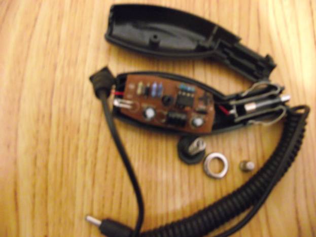
The photo shows a creative mess and the speaker is already in working order. But as you can imagine, before that it was out of service. So the task:
1. Just reanimate the speakers
2. Make them work from USB computer or a laptop (since I didn't have a power supply to power these speakers)
3. Mobility. One column is easier to carry with you to repair computers)
4. Ability to power these speakers from batteries.
Let's start reanimating the columns, for this we need: Standard set for soldering (tin, rosin, soldering iron), as well as several wires, a 180 ohm resistor, a USB extension cable - must have a male-female plug, such as are used to lengthen the mouse cable. And we will also need a charger for a sotik from a cigarette lighter. The charger is needed for Nokia phones, assembled on a microcircuit mc34063. I think you can choose a soldering iron yourself, but we need a USB cable like this:

The longer the cord, the more convenient it is to work with it. You can buy it at any computer store. In our case, this cord will be used to power the speakers via USB. The wires in the cord are colored. We need a BLACK minus and a RED plus. Any resistor can be used - I took smd at 150 ohm, I did not find it for 180 ohm. Now about the main thing! About the charger from which we will sculpt the converter.

Many chargers have been tested, but this model has proven to be the most reliable and convenient for rework.
1. You don't have to buy any additional parts, everything is already on the board (except for one resistor).
2. Immediately there is a printed circuit board, the rework of which is minimal
3. The converter board fits perfectly in the column on the mount instead of the transformer.
4. This view the charger NEVER FALSE, unlike other models - everything works right away.
5. All denominations of parts are immediately indicated on the board - this is very convenient.
6. These chargers are always assembled on the mc34063 microcircuit, which is the most important factor for us.
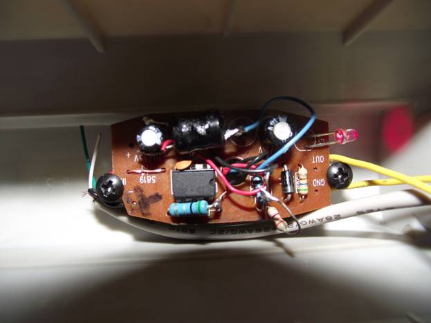
Inside Charger looks like that:
The photo came out unsuccessfully, but in principle everything is clear. This converter is assembled as a step-down converter, but we need to make a step-up from it (fortunately, this can be done without much difficulty). To make it easier for you to navigate when reworking, here are two schemes for you. A variant of a downconverter - there is simply no indicator LED in the circuit and a diode from polarity reversal, they are in the charger itself. If you assemble the circuit yourself, then I see no reason to complicate the circuit and put these elements. And in the finished scheme, I just didn't solder them, and they don't bother me.

Step-up version of the supply voltage converter:

As you can see, the rework is minimal. You just need to cut several tracks on the board and rewire the diode and the choke in places, and the choke can be left native - everything will work fine. Oh yes, I almost forgot, you will have to add one 180 ohm resistor to the circuit and that's it. If you were satisfied with the output voltage of your converter before, then you will not have to touch anything and after the alteration it will remain the same. If you need a different voltage, then just select R2 according to the scheme - the higher the voltage at the output, the more we select the resistance R2, and per turn, if the voltage at the output is less, then the resistance of the resistor is selected less. In principle, there are a lot of calculators on the network to calculate the strapping of this microcircuit, so there will be no problems with this.
In my case, a voltage of at least 10-11V was needed. Which was done by selecting the resistor R2. After alteration, this converter can be powered from 3 to 6V, which, if necessary, will allow this amplifier to be powered even from a battery. mobile phone... In this case, the output of the converter will always have a stable voltage. According to this scheme, several chargers were assembled for cell phones from batteries. The minimum power supply for the microcircuit is 3V, the maximum is 40V. You can see more details about this in the datasheet for the mc34063 microcircuit. The finished device looks like this:

Everything could fit back into the cigarette lighter housing.

The view is already inside the column. Stands instead of a standard power supply.
Here is the amplifier itself on the TDA2822 chip, on its board there are a volume control and a power switch:

For completeness, I will give a diagram from a datasheet to a TDA2822 stereo amplifier microcircuit:

Maximum allowable voltage power supply of the TDA2822 microcircuit - 10V. Although I tried from 14V, but I do not advise you to repeat, you never know. Well, that's all now your speakers can be powered from USB and from a charger for a player or sotik, or from batteries. And if you put batteries inside, it will be completely universal. See the finished column at the beginning of the article. Sent by A. Kulibin
Discuss the article SPEAKERS WITH AMPLIFIER ON TDA2822
Hello friends. Today I will tell you how to make a small power amplifier on the tda2822m microcircuit. Here is the schematic I found in the datasheet of the chip. We will be making a stereo amplifier, that is, there will be two speakers - right and left channels.
Amplifier circuit

We will need:
- Chip TDA2822m.
- 4.7 ohm resistor (2 pcs.).
- Resistor 10 kohm (2 pcs.).
- Capacitor 100 MKF (2 pcs.).
- Capacitor 10 MKF.
- Capacitor 1000 MKF (2 pcs.).
- Capacitor 0.1 MkF (2 pcs.).
- Speaker (about 4 ohms and 3 watts) (2 pcs.).
Assembling the amplifier
We will assemble the circuit on something in between the hinged installation and printed circuit board... A piece of cardboard will serve as a board; we will attach all the parts to it.For radio components, use a pin to make holes for the legs. In most cases, the legs will be in the role of tracks with which we will separate the entire circuit. The first thing we insert is the microcircuit itself, then we solder the plus leg of the 1000 uF capacitor to the very first leg.


Next, we solder a 4.7 ohm resistor to the minus leg, and a 0.1 μF capacitor to it (the capacitor has 104 marking). We also solder a wire to the negative leg of the 1000 uF capacitor, one of the speakers will go to it.


We do everything the same with the third leg of the microcircuit.
Next, we solder to the second leg of the microcircuit the plus leg of the 10 uF capacitor and the wire that will be the plus of the power supply.
To the fifth and eighth legs of the microcircuit, we solder the positive legs of the 100 uF capacitors.

We solder two wires to the sixth and seventh legs of the microcircuit - these are the right and left channels (the sixth is the right, the seventh is the left). We also solder two 10 kΩ resistors. This is where I had a problem. I found only one 10 kΩ resistor. Going to the store for one resistor is unwise, so I had to remember some of my physics lessons. Namely, how to calculate the resistance when connecting two resistors in parallel. This is what the formula looks like:

But this formula only works with two resistors, if there are more of them the formula does not work. I found resistors for 20 and 24 kΩ, these are some old Soviet resistors.

On this, almost everything is ready. It remains to deal with the ground, it will also be a power minus. All the remaining legs from the capacitors are 100; ten; 0.1 μF, as well as from 10 kΩ resistors, must be connected in one bundle. I connected all the ground on the leg of the 100 uF capacitor, in some places I had to connect with wires. Ground, also 4 leg of the microcircuit.

Also, the ground will be the minuses of the speakers. Now we solder the 3.5 mm jack. The copper wire is the ground, the red one is the right channel we solder to the sixth leg of the microcircuit (to the wire that was brought out earlier), the blue one is the left channel, we solder it to the seventh leg.

We connect the plus of each speaker to the negative leg of the 1000 uF capacitors. We solder the minuses of the speakers to the common ground. The plus of the power supply is the wire from the second leg of the microcircuit, as I said earlier, the minus of the power supply is the ground. This completes the production of the circuit. Let's cut the cardboard, if the compactness of the circuit is important, then the cardboard should initially be taken smaller, since there are few elements on the circuit.
I assembled a simple amplifier on the TDA2822M, and it started working right away
But due to an unsuccessful experiment, the micra burned out. Recently I came across a board with such a micro, and I decided to reassemble such an amp. So catch
The microcircuit, of course, does not give much, only 1W per channel, but for small speakers this is normal
Here is a circuit of a 2X1W amplifier on a TDA2822M taken from the datasheet

Nothing complicated with a minimum of details, I collected boards with weed in 20 minutes
Set of parts as usual
C1 = 1000mF (16V)
C2,4,6 = 100nF (104)
C3,7 = 470mF (16V)
C5.8 = 100mF (16V)
R1,3 = 10kΩ (brown - black - orange)
R2.4 = 4.7ohm (yellow - purple - gold)
Power supply 6-14V, 15V limit. Consumption 200mA
Assembled amplifier on printed circuit board

Signet pattern from the side of the tracks

Signet for amplifier 2X1W on TDA2822M. Just like at home. This article has all the technology
Guards: If you have any problems with Motorola or Icom radios, then this company repairs professional radios for a small price. The company's engineers have qualitatively repaired more than 4000 radio stations in the shortest possible time
Related Posts
I took out the 3GDSH-1 speakers from the TVs, so that they would not lie idle, I decided to make speakers, but since I have an external amplifier with a subwoofer, it means I will assemble satellites.
Hello everyone, dear radio amateurs and audiomaniacs! Today I will tell you how to modify the high-frequency speaker 3GD-31 (-1300) aka 5GDV-1. They were used in such acoustic systems as 10MAS-1 and 1M, 15MAS, 25AS-109 …….
Hello dear readers. Yes, I haven't written blog posts for a long time, but with all responsibility I want to declare that now I will try to keep up, and I will write reviews and articles …….
Hello dear visitor. I know why you are reading this article. Yes, yes, I know. No, what are you? I'm not a telepath, I just know why you came to this particular page. Surely …….
And again my friend Vyacheslav (SAXON_1996) wants to share his experience on the columns. Word to Vyacheslav I got one 10MAS speaker with a filter and a high-frequency speaker. I haven't …… for a long time.
Not so long ago I had an idea to practice making miniature devices. Without thinking twice, I went to the site of a regional seller of radio components and in the process of searching came across a wonderful solution in the form of a TDA2822L microcircuit. Now about our rams.
The TDA2822L is a low-power low-voltage integrated UMZCH, which has already been mentioned on this site (it seems like more than once). Its features are two channels, the ability to supply from a voltage in the range of 1.8 - 12 V (unipolar), low losses, the ability to connect via a bridge circuit and the presence of a solution in an SOP-8 package (not the smallest in nature, but still quite compact). And, by the way, "fool" he has 1 W per channel (with a 4-ohm load). That is, even with large powerful headphones, it is enough for the eyes (more on that later). And it costs $ 0.37. Fairy tale, and more!
The binding for it is minimal, and the UMZCH circuit according to the datasheet looks like this:
There is nothing fundamentally incomprehensible in this scheme, the details are typical, so let's go straight to the interesting, namely, the choice of parts.
Since we are assembling a miniature amplifier, it is clear that the maximum number of parts should be in smd version, in particular, I managed to do everything in smd except C4 and C5 (well, our store does not carry electrolytes for smd installation). As for the power supply, it is even more interesting - right from the moment the idea arose, I decided that I would power the circuit from a tablet like CR2032, since there is a wonderful small holder for them, and since almost all smd elements, the space saving is good. But then, just in case, I decided to add two patch points for the wires on the crown, just as a reserve.
In total, our list of components:
Chip TDA2822L in SOP-8 package x1.
Tantalum capacitor 100uF x 10V x3 (most expensive part).
10 kOhm resistor 0805 x2
4.7ohm resistor 0805 x2
Capacitor 0.1 uF x2
Electrolytic capacitor 470 uF> 10 V (I have 16 V) x2
The result is such a cute "baby doll":

Disclaimer: the fact that you can get rid of the R0 jumper, inherited from the previous revision of the board, I noticed after I soldered the board, so it's too late and too lazy to fix it
As you can see, the dimensions are, ahem, small. To tell the truth, I did not even expect this, although the first version of the board was a little smaller and without a mask, but after making the seal it turned out that the electrolytes would have to be left hanging in the air. Along with the poor quality of the motherboard of the first version, I slightly enlarged and redesigned it, and everything went like clockwork (to tell the truth, almost like clockwork, one capacitor still "hangs").
Note: on the board, the microcircuit itself actually stands the other way around, compared to the diptrace project.
So, having a project in hand, we make a printed circuit board (as you like, I use FR + ammonium persulfate). A few photos on how this is done at home:


A little about how I soldered the board - first the battery holder, then the stereo connectors, then the microcircuit itself, then small smd elements, at the end of the tantalum and wires to the crown. The tantalum turned out to be the most nasty (I soldered the microcircuit with a hairdryer, not counting), tk. the spots for them are completely under the capacitor - therefore, it is inconvenient.


The final cost turned out to be about $ 3. (reagents, textolite, I do not consider). Here's a demo of what this amplifier can roughly do:
Below you can download the printed circuit board in the format
List of radioelements
| Designation | Type of | Denomination | Quantity | Note | Shop | My notebook |
|---|---|---|---|---|---|---|
| Chip | TDA2822L | 1 | SOP-8 | Into notepad | ||
| C1, C2, C3 | 100 μF x 10V | 3 | Tantalum | Into notepad | ||
| C4, C5 | Electrolytic capacitor | 470 uF x 16V | 2 | Into notepad | ||
| C6, C7 | Capacitor | 0.1 uF | 2 | Film | Into notepad | |
| R1, R2 | Resistor | 10 kΩ | 2 | smd 0805 |


 Pc radio does not display channel list")
