- The FC-113 module is based on the PCF8574T chip, which is an 8-bit shift register - an I/O expander for the I2C serial bus. In the figure, the microcircuit is designated DD1.
- R1 - trimmer to adjust the contrast of the LCD display.
- Jumper J1 is used to turn on the backlight of the display.
- Pins 1…16 are used to connect the module to the pins of the LCD display.
- Contact pads A1 ... A3 are needed to change the I2C address of the device. By soldering the appropriate jumpers, you can change the address of the device. The table shows the correspondence between addresses and jumpers: "0" corresponds to an open circuit, "1" - a jumper is installed. By default, all 3 jumpers are open and the device address 0x27.
2 Wiring diagram for LCD display to Arduino via I2C protocol
The module is connected to the Arduino as standard for the I2C bus: the SDA output of the module is connected to the analog port A4, the SCL output is connected to the analog port A5 of the Arduino. The module is powered by +5 V from Arduino. The module itself is connected by pins 1…16 to the corresponding pins 1…16 on the LCD display.

3 Library for work via I2C protocol
Now we need a library for working with LCD via the I2C interface. You can use, for example, this one (link in the line "Download Sample code and library"). 
Downloaded archive LiquidCrystal_I2Cv1-1.rar unzip to a folder \libraries\, which is located in the Arduino IDE directory.
The library supports a set of standard functions for LCD screens:
| Function | Purpose |
|---|---|
| LiquidCrystal() | creates a variable of LiquidCrystal type and accepts display connection parameters (pin numbers); |
| begin() | initialization of the LCD display, setting parameters (number of lines and symbols); |
| clear() | clearing the screen and returning the cursor to its original position; |
| home() | return of the cursor to the initial position; |
| setCursor() | setting the cursor to a given position; |
| write() | displays the character on the LCD screen; |
| print() | displays text on the LCD screen; |
| cursor() | shows the cursor, i.e. underlining under the next character; |
| noCursor() | hides the cursor; |
| blink() | cursor blinking; |
| noBlink() | cancel blinking; |
| noDisplay() | turning off the display while saving all displayed information; |
| display() | turning on the display while saving all displayed information; |
| scrollDisplayLeft() | scrolling the contents of the display 1 position to the left; |
| scrollDisplayRight() | scrolling the contents of the display 1 position to the right; |
| autoscroll() | enable auto scrolling; |
| noAutoscroll() | turn off auto scroll; |
| leftToRight() | sets the text direction from left to right; |
| rightToLeft() | text direction from right to left; |
| createChar() | creates a custom symbol for the LCD screen. |
4 Sketch for text output to LCD screen via I2C bus
Let's open the sample: File Samples LiquidCrystal_I2C CustomChars and let's change it a bit. Let's display a message, at the end of which there will be a blinking character. All the nuances of the sketch are commented in the comments to the code.
#include
By the way, the characters written by the command lcd.createChar(); remain in the display memory even after the power is turned off. are written to the ROM of the display 1602.
5 Creating your own symbols for LCD display
Let's take a closer look at the issue of creating your own symbols for LCD screens. Each character on the screen consists of 35 dots: 5 wide and 7 high (+1 spare line for underlining). In line 6 of the above sketch, we define an array of 7 numbers: (0x0, 0xa, 0x1f, 0x1f, 0xe, 0x4, 0x0). Let's convert hexadecimal numbers to binary: {00000, 01010, 11111, 11111, 01110, 00100, 00000} . These numbers are nothing more than bit masks for each of the 7 lines of the character, where "0" denotes a light point, and "1" a dark one. For example, a heart symbol given as a bitmask will appear on the screen as shown in the figure.

6 LCD control via I2C bus
Upload the sketch to the Arduino. The inscription we specified will appear on the screen with a blinking cursor at the end.

7 What is behind I2C bus
As a bonus, consider the timing diagram of the output of the Latin characters "A", "B" and "C" on the LCD display. These characters are stored in the display's ROM and are displayed on the screen simply by passing their address to the display. The diagram is taken from the outputs RS, RW, E, D4, D5, D6 and D7 of the display, i.e. already after the converter FC-113 "I2C parallel bus". We can say that we are diving a little "deeper" into the "iron".
 Timing diagram for displaying Latin characters "A", "B" and "C" on the LCD display 1602
 The diagram shows that the characters that are in the display ROM (see page 11 of the datasheet, link below) are transmitted in two nibbles, the first of which determines the table column number, and the second determines the line number. In this case, the data is "latched" along the edge of the signal on the line E(Enable) and the line RS(Register select, register selection) is in a logical one state, which means data transfer. The low state of the RS line means the transmission of instructions, which we see before the transmission of each character. In this case, the code of the carriage return instruction to the position (0, 0) of the LCD display is transmitted, which can also be found out by studying the technical description of the display.
And one more example. This timing diagram shows the display of the Heart symbol on the LCD.

Again, the first two impulses enable comply with instructions Home()(0000 0010 2) - carriage return to position (0; 0), and the second two - output to the LCD display stored in memory cell 3 10 (0000 0011 2) the symbol "Heart" (instruction lcd.createChar(3, heart); sketch).
Perhaps one of the most popular screens on the market. Built on the popular HD44780U controller. From the name of the model it follows that the screen consists of two lines of 16 characters. There is no support for the Russian language in this particular model.
The sh2s data bus allows you to connect up to 127 devices via two wires, and at the same time. This I2C is implemented on the PCF8574T chip.
Wiring diagram:

Blue thing - variable resistance, allows you to adjust the contrast of the screen.
The jumper on the left is responsible for the backlight of the screen.
A block of 4 pins is connected to arduino like this:
GND-GND
VCC - 5V
SDA - A4 (if Arduino MEGA, then to D20)
SCL - A5 (if Arduino MEGA, then to D21)

Library
Sketch
The display may have a different IIC address, instead of 0x27 it may turn out to be 0x3F. To accurately determine the address, you can use the i2c device scanner.
#include
The LCD I2C module allows you to connect a character display to the Arduino board with just two signal wires.

Components used (buy from China):
. control board
. Connecting wires
Main technical characteristics:
Display: Character 16x02 or 20x04
. Illumination: Blue with white characters
. Contrast: adjustable by potentiometer
. Supply voltage: 5V
. Interface: I2C
. I2C address: 0x27
. Dimensions: 82mm x 35mm x 18mm
Connecting to Arduino
The module is equipped with a four-pin 2.54mm connector
SCL: serial clock line (Serial CLock)
SDA: serial data line (Serial DAta)
VCC: "+" power
GND: "-" power
The pins responsible for the I2C interface on Arduino boards based on different controllers vary
To work with this module, you need to install the LiquidCrystal_I2C1602V1 library
Download, unpack and drop into the libraries folder in the Arduino folder. If at the time of adding the library, the Arduino IDE was open, restart the environment.
Let's go straight to the sketch. In this example, we will display the standard "Hello, world!" and for the address of our community.
code example:
#includeCreating your own symbols
We figured out the text output, the letters of the English alphabet are sewn into the controller's memory inside the display and there are no problems with them. But what to do if the desired character is not in the controller's memory?
It doesn't matter, the required character can be made manually. This method partially, limiting to 7 characters, will help solve the output problem.
The cell, in the displays we are considering, has a resolution of 5x8 pixels. All the task of creating a symbol comes down to is writing a bit mask and placing ones in it in places where dots should burn and zeros where not.
In the example below, let's draw a smiley face.

code example:
//Tested on Arduino IDE 1.0.5 // Add the necessary libraries#includeProgram for easy creation of symbols
In the comments, a community member dropped a link to a character generator
I got here from a good Chip Resistor store another device for studying and using it in useful devices. This device turned out to be sharpened to control the LCD display under the control of the HD44780 controller, in 4-bit mode. For this purpose, a microcircuit is installed on the board, which is a converter of the I2C bus to a parallel 8-bit port.The board is divorced in such a way that it can be immediately crossed with the LCD display. The input is powered and I2C lines. The board immediately has pull-up resistors on the SCL and SDA lines, a potentiometer for adjusting the contrast, and powering the display itself.

The jumper on the right turns the backlight on/off. Then, armed with a tester, the following plate was compiled. After studying the module, it was found that P3 controls the backlight. If the jumper is set, then 1 turns on the backlight, and 0 turns it off. When the jumper is removed, the backlight is always off. Further, it was decided to supplement the axlib library with functions for working with the I2C bus (software implementation) and functions for controlling the PCF8574 chip. In a nutshell, how the module works. In order to output bytes in parallel, for this you need to send the address of the microcircuit to the I2C bus (by default it is 0x4E. You can also change the address by soldering jumpers on the board and changing the value of the three least significant digits of the address), then after receiving ACK a data byte is sent. After the chip responds with ACK, the byte appears on the parallel port of the chip. To control the LCD, I took the functions from the axlib library and slightly reworked them to work with the I2C bus. #include
BYTE pcf8574_test(BYTE add) ( BYTE ask = ACK; add &= 0xFE; i2c_start(); ask = i2c_send_byte(add); i2c_stop(); return ask; ) The first function was written to check if a device is on the bus. In principle, it can be used to search for any device located on the bus. The function takes the address of the desired device, and if it responds, it returns zero. If the device with this address is not on the bus, it will return one.
BYTE pcf8574_byte_out(BYTE data, BYTE add) ( BYTE ask = ACK; add &= 0xFE; i2c_start(); ask = i2c_send_byte(add); if(!ask) ask = i2c_send_byte(data); i2c_stop(); return ask; ) This function has already been sharpened purely for this chip. As arguments, it is passed a byte for transmission to the bus and the address of the microcircuit. The function will first query the chip at the address and then send a byte. If the chip received the byte and responded with an ACK, then the function will terminate the chip and return zero as a successful byte. And the microcircuit at this time will output this byte to its parallel port. Otherwise, we get NACK and return one, the transfer failed.
BYTE pcf8574_str_out(BYTE *data, BYTE col, BYTE add) ( BYTE ask = ACK; add &= 0xFE; i2c_start(); ask = i2c_send_byte(add); for(BYTE i=0; i
void com(BYTE com) ( com |= 0x08; // P3 to one, so that the backlight is on pcf8574_byte_out(com, ADD); // Data output com |= 0x04; // E to one pcf8574_byte_out(com, ADD); // Data output com &= 0xFB; // E to zero pcf8574_byte_out(com, ADD); // Data output
}
This function only sends commands to the display. Hence the first line appeared with the logical addition of the command from 0x08. This byaka is needed due to the fact that we do not transmit the bytes directly to the LCD port, but through our repeater. That is, if we submitted a byte, and then we need to output only one bit, then if you please, it will assign the necessary bit to the previous byte and send it to the port again. This is such a freeze. Addition with 0x08 is necessary to permanently hold one at the third digit. Remember backlight? It is this addition that turns on the backlight. After we call the function of transferring a byte to the bus. It has been written about above. Then we transfer the byte over the bus to the microcircuit. Next, you should set it to unit E, which is what the logical addition of a byte with 0x04 actually does. After zeroing E. Thus, you can send any command to the display only by passing the command itself as an argument. void init(void) ( _delay_ms(30); // Pause after power up com(0x30); // Switch to 4-bit mode _delay_us(40); // Delay for command execution com(0x30); // Switch to 4-bit mode _delay_us(40); // Delay for command execution com(0x30); // Switch to 4-bit mode _delay_us(40); // Delay for command execution com(0x20); // Switch to 4-bit mode _delay_us(40); // Delay for command execution com(0x20); // Set options com(0x80); // Set options com(0x00); // Turn off the display com(0x80); // Turn off the display com(0x00); // Clear the display com(0x10); // Clear the display com(0x00); // Set the input mode com(0x60); // Set the input mode com(0x00); // Turn on the display with the selected cursor com(0xC0); // Turn on the display with the selected cursor
}
This function is only concerned with the initialization of the display. The sequence of commands is taken from the datasheet on the LCD display. void char_out(BYTE data) ( BYTE data_h = ((data & 0xF0) + 0x09); BYTE data_l = ((data // Pass high 4 bits data_h |= 0x04; pcf8574_byte_out(data_h, ADD); // Pass high 4 bits data_h &= 0xF9; pcf8574_byte_out(data_h, ADD); // Pass high 4 bits pcf8574_byte_out(data_l, ADD); // Pass low 4 bits data_l |= 0x04; pcf8574_byte_out(data_l, ADD); // Pass low 4 bits data_l &= 0xF9; pcf8574_byte_out(data_l, ADD); // Pass low 4 bits
}
This function sends data to the LCD. It is performed in the same way as commands, except that the transmission of a byte goes first with the high nibble, and then with the low one. And the rest is the same. void str_out(BYTE *str) ( while((*str) != "\0") ( char_out(*str); str++; ) ) Well, this function is purely for passing a string to the display. Actually, it has nothing to do with our topic.

Project for AtmelStudio 6.2
Competent 01.08.15 17:11
The comma is missing. Correct: "HELLO WORLD!" And this device is sharpened not only for HD44780. Pull-up resistors are placed from the side of the master. According to the specification, data is written to the LCD controller in descending E. From here, the first function is simplified: void com(BYTE com) ( com |= 0x08; // backlight pcf8574_byte_out(com | 0x04, ADD);// Data output pcf8574_byte_out(com , ADD); // E to zero ) Yes, and the rest can also be significantly less. For example, void char_out(BYTE data) will be just two calls, and even more so without additional variables. The LCD initialization was performed with violations of the timings specification.
Alexey 02.08.15 19:11
Due to the lack of a comma, the display will not suffer. This device is just designed specifically for displays with this or a similar controller. But it is the microcircuit that is really a simple port expander. I agree about E. Additional variables are needed. If you pass an argument to a function and perform some actions with logic, glitches may occur. Already encountered this. Initialization is performed without timing violations. The documentation says that there is a pause of 40 µs between commands. Due to the fact that the transfer goes through the i2c bus, which, in turn, is software and slow, the periods are more than fulfilled. If you are not too lazy, then write your own version and send it to me. I will publish it. In the end, this site is intended for an amateur audience and anyone who wants to can express their opinion and vision for the life of MK.
Alexey 06.08.15 09:14
Added timings when initializing the display at the remark of the respected "Competent"
Dmitry 14.06.16 21:57
Hello Alexey. You can add a library to the code generator to work with PCF8574.
Alexey 14.06.16 22:32
I will think.))
ruslan 21.12.16 19:54
Alexey 21.12.16 21:53
Oh yeah. Especially the code on asma. Arduiners will appreciate it to the fullest)))
Py.sy.
Even if you do not look at asm, then there the program is written under the PIC controller. Is this "very" useful information for AVR people? especially for beginners))) I have nothing against PIC, but even PIC and AVR have different asm. And as for the details of the LCD display, you can look))) True, I also wrote it under CVAVR, but all the commands were sorted and sorted. But in any case, decide for yourself where it is written more clearly))) The author writes, the reader chooses.
GeK 04.01.17 12:52
"I2C chip address (default is 0x4E"
The upper 4 bits of the address are fixed,
prefix PCF8574 is 0100 and PCF8574A is 0111
The lower 3 bits depend on the state of the inputs of the A2-A0 microcircuit. By default, all 3 jumpers are open, respectively, the address of the microcircuit is 0111111.
// A2 A1 A0 PCF8574 PCF8574A
// 1 1 1 0x20 0x38
// 1 1 0 0x21 0x39
// 1 0 1 0x22 0x3A
// 1 0 0 0x23 0x3B
// 0 1 1 0x24 0x3C
// 0 1 0 0x25 0x3D
// 0 0 1 0x26 0x3E
// 0 0 0 0x27 0x3F
Alexey 04.01.17 14:27
You mixed up something.
Extract from the documentation for the microcircuit

0b01001110 is 0x4E
So everything is right here. And if you need to change the address, then you just need to change it in the define.
Yuri 14.12.17 21:26
Good day! And you can also use the lcdgotoxy and lcdclear function code to work with the adapter on the PCF8574.
Alexander 20.05.18 18:14
Good day! how do you display Russian text.
Alexey 05/20/18 23:04
This is a domestic display from MELT. He has the Cyrillic alphabet sewn into his memory.
Alexander 21.05.18 04:55
Good day! I write like you have in the Project for AtmelStudio 6.2 "ЁPҐBET MҐP!" it outputs fine
and if you write "HELLO WORLD!" brings out all kinds of nonsense. I have two
variant of displays in one is sewn up in Cyrillic. second Chinese.
Alexey 05/21/18 09:22
I would write a test program first. Enumeration of the entire memory with the display of characters and their addresses. And then figure out what the problem is. Most likely the character table does not match the ascii table.
Andrey 03.09.18 08:32
Good afternoon!
Can't you upload a schematic for Proteus?
Andrey 03.09.18 10:22
Or no one checked in Proteuse?
Andrey 03.09.18 10:56
Figured out main_init
Pavel 05/30/19 23:35
A curious thing, the display address is 0x4E, and if the same display is connected to an arduino, then the address is 0x27
Pavel 05/31/19 11:04
Thank you very much for your work! I've looked all over the internet and none of the above examples work except for yours. The only thing is that in the project archive, the _delay_ delays are not registered in the display initialization function, and it does not work accordingly
Alexey 06/01/19 09:52
Well, this is more of a demo project. For good, you need to rewrite the axlib library, but given the fact that STM32 and STM8 are moving by leaps and bounds, there is no point in AVR at all.
Pavel 05.06.19 12:57
STM does not have DIP packages, it is more difficult to make printed circuit boards. For my projects, the AVR capabilities are enough with a margin, a lot can fit on one Atmega 8
Alexey 05.06.19 15:20
Yes, but how much does Atmega8 and stm8s003 cost)))
Dmitry 06/07/19 00:41
Hello Alexey.
Can you please tell me how to read the port status from pcf8574?
I want to make an external unit, 8 GPIOs on the i2c bus - that's it.
Dmitry 07.06.19 17:56
I will answer myself
The function returns a byte - the state of the microcircuit ports
uint8_t pcf8574_byte_rcv(uint8_t addr)
{
uint8_t ask = ACK;
addr |= 0b01; //READ
uint8_tdata=0;
i2c_start();
ask = i2c_send_byte(addr);
if(!ask) data = i2c_read_byte(NACK);
i2c_stop();
return data;
}
Pavel 06/07/19 20:37
How much does it cost, 150 rubles, for the price of a relay in general), but how do you breed boards for STM? LUT is unreliable, CNC router is not sure what it will take (did not try)
LCD display- a frequent guest in arduino projects. But in complex circuits, we may have the problem of a lack of Arduino ports due to the need to connect a shield that has a lot of pins. The way out in this situation can be I2C/IIC an adapter that connects an almost standard Arduino 1602 shield to Uno, Nano or Mega boards with just 4 pins. In this article, we will see how you can connect an LCD screen with an I2C interface, what libraries you can use, write a short sketch example and analyze typical errors.
Liquid Crystal Display LCD 1602 is a good choice for outputting character strings in various projects. It is inexpensive, there are various modifications with different backlight colors, you can easily download ready-made libraries for Arduino sketches. But the main disadvantage of this screen is the fact that the display has 16 digital pins, of which at least 6 are required. Therefore, using this LCD screen without i2c adds serious limitations for Arduino Uno or Nano boards. If there are not enough contacts, then you will have to buy an Arduino Mega board or save contacts, including by connecting the display via i2c.
Brief description of LCD 1602 pins
Let's take a closer look at the LCD1602 pins:
Each of the conclusions has its purpose:
- Ground GND;
- Power supply 5 V;
- Setting the monitor contrast;
- Command, data;
- Writing and reading data;
- enable;
7-14. Data lines;
- Plus backlight;
- Minus backlight.
Display specifications:
- Symbolic display type, it is possible to load symbols;
- Neon lights;
- Controller HD44780;
- Supply voltage 5V;
- Format 16x2 characters;
- Operating temperature range from -20C to +70C, storage temperature range from -30C to +80C;
- Viewing angle 180 degrees.
Wiring diagram for LCD to Arduino board without i2C
The standard scheme for connecting a monitor directly to an Arduino microcontroller without I2C is as follows.

Due to the large number of contacts to be connected, there may not be enough space to connect the necessary elements. Using I2C reduces the number of wires to 4 and busy pins to 2.
Where to buy LCD screens and shields for arduino
The LCD screen 1602 (and the 2004 version) is quite popular, so you can easily find it both in domestic online stores and on foreign sites. Here are some links to the most available options:
  LCD1602+I2C blue screen module compatible with Arduino LCD1602+I2C blue screen module compatible with Arduino
|   Simple LCD1602 display (green backlight) cheaper than 80 rubles Simple LCD1602 display (green backlight) cheaper than 80 rubles
|   Large screen LCD2004 with I2C HD44780 for arduino (blue and green backlight) Large screen LCD2004 with I2C HD44780 for arduino (blue and green backlight)
|
 Display 1602 with IIC adapter and blue backlight Display 1602 with IIC adapter and blue backlight
|  Another version of LCD1602 with a soldered I2C module Another version of LCD1602 with a soldered I2C module
|   Port IIC/I2C/TWI/SPI Adapter Module for 1602 Shield Compatible with Arduino Port IIC/I2C/TWI/SPI Adapter Module for 1602 Shield Compatible with Arduino
|
  RGB backlit display! LCD 16×2 + keypad +Buzzer Shield for Arduino RGB backlit display! LCD 16×2 + keypad +Buzzer Shield for Arduino
|  Shield for Arduino with buttons and screen LCD1602 LCD 1602 Shield for Arduino with buttons and screen LCD1602 LCD 1602
|  LCD display for 3D printer (Smart Controller for RAMPS 1.4, Text LCD 20×4), SD and MicroSD card reader module LCD display for 3D printer (Smart Controller for RAMPS 1.4, Text LCD 20×4), SD and MicroSD card reader module
|
Description of the I2C protocol
Before discussing connecting a display to an arduino via an i2c adapter, let's briefly talk about the i2C protocol itself.
I2C / IIC(Inter-Integrated Circuit) is a protocol originally created for interconnecting integrated circuits within an electronic device. The development belongs to Philips. The i2c protocol is based on the use of an 8-bit bus, which is needed to connect blocks in the control electronics, and an addressing system, thanks to which you can communicate with several devices over the same wires. We simply transfer data to one or another device, adding the identifier of the desired element to the data packets.
The simplest I2C circuit may contain one master (most often an Arduino microcontroller) and several slaves (for example, an LCD display). Each device has an address in the range from 7 to 127. There should not be two devices with the same address in the same scheme.
The Arduino board supports i2c in hardware. You can use pins A4 and A5 to connect devices using this protocol.
There are several advantages to working with I2C:
- Only 2 lines are required for operation - SDA (data line) and SCL (clock line).
- Connection of a large number of leading devices.
- Reducing development time.
- Only one microcontroller is required to control the entire set of devices.
- The possible number of microcircuits connected to one bus is limited only by the maximum capacity.
- High degree of data safety due to a special surge suppression filter built into the circuits.
- Simple procedure for diagnosing emerging failures, fast troubleshooting.
- The bus is already integrated into the Arduino itself, so there is no need to develop an additional bus interface.
Disadvantages:
- There is a capacitive limit on the line - 400 pF.
- Difficulty programming the I2C controller if there are several different devices on the bus.
- With a large number of devices, it becomes difficult to localize a failure if one of them incorrectly sets a low level state.
i2c module for LCD 1602 Arduino
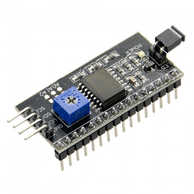 The fastest and most convenient way to use an i2c display in arduino is to buy a ready-made screen with built-in protocol support. But these screens are not very much and they are not cheap. But a huge number of various standard screens have already been released. Therefore, the most affordable and popular option today is to buy and use a separate I2C module - an adapter that looks like this:
On one side of the module, we see the i2c pins - ground, power and 2 for data transfer. On the other adapter we see the external power connectors. And, of course, there are many pins on the board, with the help of which the module is soldered to the standard screen pins.


I2c outputs are used to connect to the Arduino board. If necessary, connect an external power supply for lighting. With the built-in trimmer we can adjust the adjustable contrast values J
On the market, you can find LCD 1602 modules with already soldered adapters, their use is maximally simplified. If you bought a separate adapter, you will need to pre-solder it to the module.
Connecting LCD screen to Arduino via I2C
To connect, you need the Arduino board itself, a display, a breadboard, connecting wires and a potentiometer.
If you are using a special separate i2c adapter, then you must first solder it to the screen module. It is difficult to make a mistake there, you can be guided by such a scheme.

An i2c-enabled LCD monitor is connected to the board using four wires - two wires for data, two wires for power.
- The GND pin is connected to GND on the board.
- The VCC pin is 5V.
- SCL is connected to pin A5.
- SDA is connected to pin A.
And it's all! No cobwebs of wires, in which it is very easy to get confused. At the same time, we can simply entrust the entire complexity of the implementation of the i2C protocol to libraries.
Libraries for working with i2c LCD display
To interface Arduino with LCD 1602 via the I2C bus, you will need at least two libraries:
- The Wire.h library for working with I2C is already available in the standard Arduino IDE program.
- The LiquidCrystal_I2C.h library, which includes a wide variety of commands for controlling the monitor via the I2C bus and allows you to make the sketch easier and shorter. You need to additionally install the library After connecting the display, you need to additionally install the LiquidCrystal_I2C.h library
After connecting all the necessary libraries to the sketch, we create an object and can use all its functions. For testing, let's load the following standard sketch from the example.
#include
Description of the functions and methods of the LiquidCrystal_I2C library:
- home() and clear() - the first function allows you to return the cursor to the beginning of the screen, the second also, but at the same time deletes everything that was on the monitor before.
- write(ch) - allows you to print a single character ch to the screen.
- cursor() and noCursor() - show/hide the cursor on the screen.
- blink() and noBlink() - the cursor blinks/doesn't blink (if its display was enabled before).
- display() and noDisplay() - allows you to enable/disable the display.
- scrollDisplayLeft() and scrollDisplayRight() - scrolls the screen one character left/right.
- autoscroll() and noAutoscroll() - allows you to enable/disable the autoscroll mode. In this mode, each new character is written in the same place, replacing what was previously written on the screen.
- leftToRight() and rightToLeft() - Sets the direction of the displayed text - left to right or right to left.
- createChar(ch, bitmap) - Creates a character with code ch (0 - 7) using an array of bitmap bitmaps to create black and white points.
Alternative library for working with i2c display
In some cases, when using the specified library with devices equipped with PCF8574 controllers, errors may occur. In this case, the LiquidCrystal_PCF8574.h library can be offered as an alternative. It extends LiquidCrystal_I2C, so there shouldn't be any problems using it.
i2c lcd display connection problems
If you don't see anything on the display after uploading the sketch, try the following steps.
First, you can increase or decrease the contrast of the monitor. Often the characters are simply not visible due to the contrast and backlight mode.
If this does not help, then check the correct connection of the contacts, whether the backlight is powered. If you used a separate i2c adapter, then check again the quality of the soldering of the contacts.
Another common reason for the lack of text on the screen can be the wrong i2c address. Try first to change the device address in the sketch from 0x27 0x20 or to 0x3F. Different manufacturers may have different default addresses. If this does not help, you can run the i2c scanner sketch, which scans all connected devices and determines their address by brute force. An example sketch of an i2c scanner.
If the screen still does not work, try unsoldering the adapter and connecting the LCD in the usual way.
Conclusion
In this article, we have covered the main issues of using the LCD screen in complex Arduino projects when we need to save free pins on the board. A simple and inexpensive i2c adapter will allow you to connect a 1602 LCD screen, occupying only 2 analog pins. In many situations this can be very important. The price for convenience is the need to use an additional module - a converter and a library. In our opinion, this is not a high price for convenience, and we highly recommend using this feature in projects.


 meter - prefix to a digital multimeter")


 Musical term rhythm")


