Good day dear radio amateurs!
I welcome you to the site ""
What is a microcontroller and why is it needed. Let's look at its definition:
- a microcircuit designed to control electronic devices, or in another way - a simple computer (micro-computer) capable of performing simple tasks.
That is, in fact, a microcontroller is a device that allows us to realize our ideas (even crazy ones), but, of course, within its capabilities. And most importantly, the realization of an idea is achieved not by the creation of sophisticated electronic structures, but only, basically, by the power of our thought (would you like to become a wizard?).
The most popular among radio amateurs are two types of microcontrollers:
– PIC- Microchip Technology
– AVR- by Atmel
I would like to make a short digression and clarify one of my positions. I am not going to discuss the merits of this or that type of microcontrollers, this or that software, and in general everything related to microcontrollers, to advise something, and even more so, to impose on readers. It's all a matter of taste, personal preference, and your ultimate goals in learning microcontrollers. Well, since “the immensity cannot be embraced”, I will conduct all my further narration in relation to AVR microcontrollers and, not very common, but my favorite, the “Algorithm Builder” program. Different types of microcontrollers, programs, of course, have differences, but they also have much in common. And we will learn the world of microcontrollers in such a way that later, the knowledge gained could be applied to PICs and any software without any problems. And let me remind you once again that this series of articles is my attempt to help those who first heard about the existence of microcontrollers and want to understand how to work with them.
What do you need to learn how to work with microcontrollers? I would single out a few, in my opinion, the main conditions:
1. Desire and perseverance
.
Everything is very simple here: there is a desire - everything will work out. And desire with perseverance is, in general, a super thing.
2. Knowledge of the microcontroller device.
Deep knowledge is not important here (and maybe not needed at all), but it is necessary to know what is “on board” the microcontroller. Only knowing what the microcontroller consists of, what devices it has, their capabilities, how they work - only then will we be able to use the capabilities of the microcontroller to its fullest.
3. Knowledge of the programming language and microcontroller control commands.
How the microcontroller will work, what tasks you assign to it and how it will perform them, is determined by the program embedded in it - the program that you yourself compose for the microcontroller. And we will dwell on this point in more detail in order to consider issues that may arise in the future.
Program(in translation, this word means “prescription”) - a preliminary description of upcoming events or actions.
For example, we want the microcontroller to blink an LED. A simple task, but nevertheless, in order for the microcontroller to complete this task, we must first, step by step, describe all the actions of the microcontroller, write a program that it must execute to obtain the result we need - a blinking LED. Something like this:
♦ Light up the LED:
- configure the output to which the LED is connected to work on the output of information
- apply a logic level to this pin, which will allow you to light the LED
♦ Wait a while:
- go to the subroutine that forms a pause (which also needs to be “chewed”)
- upon completion of the pause subroutine, return to the main program
♦ Turn off the LED:
- apply a logic level to the output, extinguishing the LED
and so on.
with the term Program another term is inextricably linked - Algorithm(like the Wolf and the Hare, Tom and Jerry).
Algorithm- a set of instructions that describe the procedure for achieving the desired result.
If in the program we are in the most detailed way prescribe actions microcontroller, then in the algorithm we determine the course of action microcontroller, on the basis of which we will then create a program. Similar to the example above:
♦ Light up the LED
♦ Wait a while
♦ Turn off the LED
and so on.
In this way, the algorithm is the forerunner of the program. And the more carefully and thoughtfully an algorithm is created, the easier it will be to create a program.
In total, the program for the microcontroller is a sequence of actions of the microcontroller in the form of a set of commands and instructions that it must execute in order to achieve our goals.
Commands for the microcontroller look like a set of ones and zeros:
00110101 011000100
so called - command codes, and command codes are the language that the microcontroller understands. And in order to translate our algorithm from Russian into the language of the microcontroller - into these very sets of zeros and ones, there are special programs.
These programs allow us to describe the order of work for the microcontroller in a language that is more or less understandable to us, and then translate this order into a language understandable to the microcontroller, resulting in the so-called machine code- a sequence of commands and instructions (the very zeros and ones) that the microcontroller understands only. The text of a program written by a programmer is called source code. The program is translated from the programming language (source code) into the microcontroller language (machine code) translators. The translator converts the program text into machine codes, which are then written to the microcontroller's memory.
In such programs, the order of operation of the microcontroller is described by a special language - the programming language. The programming language is different from our human language. If our language of communication is primarily for exchanging information, then:
Programming language - this is a way of transmitting commands, instructions, a clear guide to action for the microcontroller.
There are many programming languages and they can be divided into two types:
– low level programming languages
– high level programming languages
What is the difference. And they differ in their proximity to the microcontroller.
At the dawn of the emergence of microprocessor technology, programs were written in machine codes, that is, the entire algorithm of work was sequentially written in the form of zeros and ones. This is what the program looked like:
01000110
10010011
01010010
It is unlikely that anyone will be able to figure out such a set of combinations of two numbers, and the work of the first programmers was very laborious. To make their lives easier, programmers began to create the first programming languages. So, the closer the programming language is to such a set of zeros and ones, the more “low level” it is, and the farther from them, the more “high level”.
The most common programming languages for microcontrollers:
- low level language - assembler
– high level language – C (Ci)
Let's look at an example of their difference (these examples are abstract).
Let's say we need to add two numbers: 25 and 35.
In native code, this command might look like this:
00000101 1101001
In low level language:
ADD Rd, Rr
In high level language:
25+35
The difference between low-level and high-level languages is visible to the naked eye, comments, as they say, are superfluous.
But let's dig deeper into these examples. We will not analyze the example of machine code, since it is identical to the example in assembler. At its core, Assembly instructions are the same machine codes (commands) that are simply assigned letter abbreviations in order not to get lost in zeros and ones. With the assembler instruction ADD Rd, Rr, we set the microcontroller to add the two numbers that are found (and for this we must first write them there) - the first in Rd, the second in Rr, and place the result of the addition in Rd. As you can see, we set a very specific task for the microcontroller: where to get it, what to do with it, and where to put the result. In this case, we work directly with the microcontroller.
Command in high-level language: 25+35 , a mathematical notation familiar to us, pleasing to our eyes. But in this case, we do not work directly with the microcontroller, we simply set it the task of adding two numbers. The result and the sequence of actions in this case will be the same as when executing the assembler command: first, these two numbers will be written somewhere, then added up and the result placed somewhere.
And here lies the main difference between high-level and low-level languages. If in Assembler we control the whole process (whether we like it or not): we know where these two numbers are written, and we know where the result will be, then in a high-level language we do not control the process. The program itself decides where to pre-write the numbers and where to place the result. In most cases, we don’t need to know this, because for us the main result is the number 60 in the output. As a result, programs in high-level languages are more readable, pleasing to the eye and smaller in size - after all, we don’t have to “climb into all holes” and paint every step of the microcontroller, the program does this later for us when it compiles it - translates it into machine codes . But there is also a downside. Two identical algorithms written in Assembler and in C, after converting them to machine codes, will have a different size: a program written in Assembler will be 20-40% shorter than a program written in C - the devil knows which way C goes to achieve the result we need . And there are cases when there is no trust in a high-level language and in a C program they insert code written in Assembler.
Professional programmers, as a rule, know several programming languages (or work in a team that includes specialists in different languages), creatively combining their features and benefits in one program. Well, we, amateurs, need to know at least one language (for starters), and we need to start (and I am firmly convinced of this, and no one will convince me) from a low-level language - Assembly.

Well, I think, and here everything is clear to us - you need to learn a programming language, in a different way - no way.
Commands and instructions for controlling the microcontroller.
AVR microcontrollers have more than 130 different commands that allow it to realize all the possibilities inherent in it. But I’ll say right away that few amateurs know them all, let alone use them all. Usually, in amateur practice, there is enough knowledge and half of the teams, or even less. But you need to learn commands. The more commands you know, the more sophisticated (in a good sense of the word) and more elegant programs will be.
Arithmetic logic unit and memory organization - program memory, data memory, non-volatile memory
♦
♦
♦
In this tutorial on avr, I tried to describe all the most basic things for beginners to program microcontrollers. avr. All examples are built on a microcontroller atmega8. This means that to repeat all the lessons you will need only one MK. As an electronic circuit emulator, Proteus is used - in my opinion, the best option for beginners. The programs in all examples are written on the C compiler for avr CodeVision AVR. Why not in some assembler? Because the beginner is already loaded with information, and the program that multiplies two numbers takes about a hundred lines in assembler, and they use C in complex bold projects. The CodeVision AVR compiler is sharpened for atmel microcontrollers, has a convenient code generator, a good interface and directly from it can be flashed by the microcontroller.
This tutorial will show and explain with simple examples how to:
- Start programming microcontrollers, where to start, what you need for this.
- What programs to use to write firmware for avr, to simulate and debug code on a PC,
- What peripheral devices are inside the MK, how to control them using your program
- How to write the finished firmware to the microcontroller and how to debug it
- How to make a PCB for your device
- Proteus is an emulator program (you can develop a circuit in it without resorting to real soldering and then test our program on this circuit). We will first launch all projects in Proteus, and then we can already solder a real device.
- CodeVisionAVR is a C programming language compiler for AVR. In it, we will develop programs for the microcontroller, and it will be possible to flash a real MK directly from it.
 He offers us to see the projects that go with him, we politely refuse. Now let's create the simplest circuit in it. To do this, click on the icon visually nothing happens. Now you need to click on the small letter R (select from library) in the component list panel, the component selection window will open
  in the mask field, enter the name of the component that we want to find in the library. For example, we need to add a mega8 microcontroller
 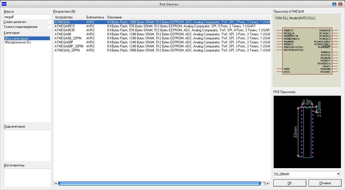 in the list of results, poke on mega8 and press the button OK. We have a mega8 microcontroller in the list of components
  Thus, we add another resistor to the list of components by entering the word in the mask field res and LED led

 To place parts on the diagram, click on the part, then click on the diagram field, select the location of the component and click again. To add a ground or a common minus to the circuit on the left, click "Terminal" and select Ground. Thus, adding all the components and connecting them, we get such a simple circuit
  Everything, now our first scheme is ready! But you might be asking, what can she do? But nothing. Nothing, because in order for the microcontroller to work, you need to write a program for it. A program is a list of instructions that the microcontroller will execute. We need the microcontroller to install on a leg PC0 logic 0 (0 volts) and logic 1 (5 volts).
 Writing a Program for a Microcontroller
We will write the program in C language using the CodeVisionAVR compiler. After launching CV, it asks us what we want to create: Source or Project We select the latter and press the OK button. Next, we will be asked to run the CVAVR CodeWizard (this is an invaluable tool for a beginner, because it can generate the main skeleton of the program)
  choose Yes
 The wizard starts with the Chip tab active, here we can select the model of our MK - this is mega8, and the frequency at which the MK will operate (mega8 is set to 1 megahertz by default), so we set everything as shown in the screenshot above. Go to the Ports tab
  The atmega8 microcontroller has 3 ports: Port C, Port D, Port B. Each port has 8 pins. Port pins can be in two states:
 - Exit
- DDRx.y = 0 - output works like INPUT
- DDRx.y = 1 pin works on EXIT
#include
Everything here may seem scary and unfamiliar to you, but in reality everything is not so. The code can be simplified by throwing out the initialization of the MK peripherals that we do not use. After simplification it looks like this:
#include
Everything is fine. But in order for the LED to blink, we need to change the logic level on the PC0 leg. To do this, add a few lines to the main loop:
#include
Everything, now the code is ready. We click on the Build all Project files icon to compile (translate into MK processor instructions) our program. In the Exe folder, which is located in our project, a file with the hex extension should appear, this is our firmware file for the MK. In order to feed our firmware to the virtual microcontroller in Proteus, you need to double-click on the image of the microcontroller in Proteus. A window like this will appear
 click on the folder icon in the Program File field, select hex - the file of our firmware and press the OK button. Now we can run the simulation of our circuit. To do this, click the "Play" button in the lower left corner of the Proteus window.
I have said more than once or twice that the study of MK should begin with assembler. A whole course on the site was devoted to this (although it is not very consistent, but gradually I comb it to an adequate look). Yes, it is difficult, the result will not be on the first day, but you will learn to understand what is happening in your controller. You will know how it works, and not copy other people's sources like a monkey and try to understand why it suddenly stopped working. In addition, it is much easier for C to mess with redneck code that will come out with a pitchfork at the most inopportune moment.
Unfortunately, everyone wants results immediately. Therefore, I decided to go the other way - to make a tutorial on C, but with a demonstration of his underwear. A good embedder programmer always holds his piece of iron tightly by the greave, preventing it from taking a single step without permission. So what will be the C code first, then what the compiler gave birth to and how it all works in reality :)
On the other hand, C's strong point is code portability. If, of course, to write everything correctly. Separating work algorithms and their iron implementations into different parts of the project. Then, in order to transfer the algorithm to another MK, it will be enough to rewrite only the interface layer, where all the access to the hardware is written, and leave all the working code as it is. And, of course, readability. The Sish source code is easier to understand at a glance (although .. for example, I don’t care what to flick on - at least si, at least asm :)), but, again, if everything is written correctly. I will also pay attention to these points.
As an experimental piece of iron on which the lion's share of all examples will be placed, my debug board will be.
First C program for AVR
Choosing a Compiler and Installing an Environment
There are many different C compilers for the AVR:
First of all, this IAR AVR C- almost unequivocally recognized as the best compiler for AVR, tk. the controller itself was created in close collaboration between Atmel and specialists from IAR. But you have to pay for everything. And this compiler is not only expensive commercial software, but it also has such a plethora of settings that you just have to work hard to compile it in it. I really didn’t have a friendship with him, the project rotted due to strange errors at the linking stage (later I found out that it was a crooked crack).
Second goes WinAVR GCC is a powerful optimizing compiler. Full open source, cross-platform, in general, all the joys of life. It also integrates perfectly into AVR Studio, allowing you to debug right there, which is hellishly convenient. In general, I chose it.
Also have CodeVision AVR C is a very popular compiler. It became popular due to its simplicity. You can get a working program in it in a few minutes - the start code wizard greatly contributes to this, stamping the standards for initializing any uarts. To be honest, I somehow treat him with suspicion - once I had to disassembly a program written by this compiler, some kind of porridge and not code turned out. A terrible amount of unnecessary gestures and operations, which resulted in a rather large amount of code and slow performance. However, perhaps there was an error in the DNA of the original firmware writer. Plus he wants money. Not as much as IAR, but noticeable. And in demo mode it allows you to write no more than 2kb of code.
Of course there is a crack, but if you steal, then a million, in the sense of IAR :)
There is also Image Craft AVR C and MicroC from microelectronics. Haven't had to use either, but... SWG very much praises micropascal, they say, a terribly convenient programming environment and libraries. I think MicroC will be no worse, but also paid.
As I said, I chose WinAVR for three reasons: free, it integrates into AVR Studio and just a bunch of ready-made code is written for it for all occasions.
So download WinAVR with and AVR Studio. Next, the studio is first installed, then, from above, WinAVR rolls up and clings to the studio in the form of a plug-in. I strongly recommend to put WinAVR on a short path, something like C:\WinAVR, thus you will avoid a lot of problems with paths.
Project creation
So, the studio is set up, C is screwed on, it's time to try to program something. Let's start with the simple, the simplest. Run the studio, select a new project there as the AVR GCC compiler and enter the name of the project.
The workspace opens with an empty *.c file.
Now it does not hurt to configure the display of paths in the bookmarks of the studio. To do this, go to:
Menu Tools - Options - General - FileTabs and select "Filename Only" from the drop-down list. Otherwise, it will be impossible to work - the tab will contain the full path of the file and there will be no more than two or three tabs on the screen.
Project setup
In general, it is considered classic to create a make file in which all dependencies would be described. And this is probably correct. But for me, who grew up with fully integrated IDEs like uVision or AVR Studio this approach is deeply alien. Therefore, I will do it in my own way, by all means of the studio.
Click on the gear button.
 |
These are the settings for your project, or rather, the settings for automatic generation of the make file. On the first page, you just need to enter the frequency at which your MK will work. It depends on the fuse bits, so we assume that the frequency is 8000000Hz.
Also pay attention to the optimization line. Now there is -Os is size optimization. Leave it as is for now, then you can try to play around with this parameter. -O0 is no optimization at all.
The next step is to set up the paths. First of all, add the directory of your project there - you will put third-party libraries there. The path ".\" will appear in the list
The make file is generated, you can look at it in the default folder in your project, just take a look, see what is there.
 |
That's all for now. Click OK everywhere and go to the source.
Formulation of the problem
A blank slate is tempting to embody some kind of cunning idea, since the banal flashing of a diode no longer inserts. Let's immediately take the bull by the horns and implement a connection with the computer - this is the first thing I do.
It will work like this:
When a unit arrives at the COM port (code 0x31), we will turn on the diode, and when zero arrives (code 0x30), we will extinguish it. Moreover, everything will be done on interrupts, and the background task will be the blinking of another diode. Simple and meaningful.
Assembling the scheme
We need to connect the USB-USART converter module to the USART pins of the microcontroller. To do this, we take a jumper of two wires and put them on the pins crosswise. That is, we connect the Rx of the controller with the Tx of the converter, and the Tx of the converter with the Rx of the controller.
It turns out, in the end, this is the scheme:
 |
I do not consider connecting the remaining outputs, power supply, reset, it is standard
We write the code
I’ll make a reservation right away that I will not delve specifically into the description of the C language itself. To do this, there is simply a colossal amount of material, ranging from the classic "C Programming Language" from K&R to various manuals.
One such method was found in my stash, I once studied this language using it. Everything is short, clear and to the point. I am gradually typing it up and dragging it to my site.
It's true that not all chapters have been moved there yet, but I think it's not for long.
It is unlikely that I will describe it better, therefore, from the training course, instead of a detailed explanation of the intricacies of the Cish, I will simply give direct links to individual pages of this manual.
Adding libraries.
First of all, we add the necessary libraries and headers with definitions. After all, C is a universal language and it needs to be explained that we are working with AVR, so enter the line into the source code:
| 1 | #include |
#include
This file is located in the folder WinAVR and it contains a description of all the registers and ports of the controller. And everything is tricky there, with reference to a specific controller, which is transmitted by the compiler through make file in parameter MCU and based on this variable, a header file with a description of the addresses of all ports and registers for this particular controller is connected to your project. How! Without it, you can too, but then you won't be able to use symbolic register names like SREG or UDR, and you'll have to remember the address of each like "0xC1", and that's breaking your head.
The very same team #include<имя файла> allows you to add the contents of any text file to your project, for example, a file with a description of functions or a piece of other code. And so that the directive could find this file, we indicated the paths to our project (the WinAVR directory is already registered there by default).
main function.
A C program is all about functions. They can be nested and called from each other in any order and in many different ways. Each function has three required parameters:
- Return value, for example, sin(x) returns the value of the sine of x. As in mathematics, in short.
- The transferred parameters, the same x.
- Function body.
All values passed and returned must be of some type, depending on the data.
Every C program must contain a function main as an entry point to the main program, otherwise it's not C at all :). By the presence of main in someone else's source of a million files, you can understand that this is the main part of the program from where everything begins. Here we will set:
| 1 2 3 4 5 | int main(void ) ( return 0 ; ) |
int main(void) ( return 0; )
That's it, the first simplest program has been written, it doesn't matter that it does nothing, we've only just begun.
Let's see what we did.
int is the data type that the main function returns.
Of course, in the microcontroller main in principle, nothing can be returned, and in theory it should be void main(void), but GCC is originally sharpened on the PC and there the program can return the value to the operating system upon completion. Therefore GCC on void main(void) swears by Warning.
This is not a mistake, it will work, but I don't like warnings.
void this is the type of data we are passing to the function, in this case main also cannot accept anything from the outside, the poet void- empty. A stub is used when nothing needs to be passed or returned.
Here are these { } curly brackets is a program block, in this case the body of the function main, the code will be located there.
return- this is the return value that the main function will give upon completion, since we have an int, that is, a number, then we must return a number. Although it still does not make sense, because. on the microcontroller from main, we can only go nowhere. I return null. For nefig. And the compiler is usually smart and does not generate code for this case.
Although, if perverted, then from main you can go to the MK - for example, fall out into the bootloader section and execute it, but here you will already need low-level picking of the firmware in order to correct the transition addresses. Below you will see and understand how to do it. What for? Now this is another question, in 99.999% of cases this is not necessary :)
Done, move on. Let's add a variable, we don't really need it and we shouldn't introduce variables without it, but we're learning. If variables are added inside the function body, then they are local and exist only in this function. When you exit the function, these variables are deleted, and the RAM memory is given to more important needs. .
| 1 2 3 4 5 6 | int main(void ) ( unsigned char i; return 0 ; ) |
int main(void) ( unsigned char i; return 0; )
unsigned means unsigned. The fact is that in the binary representation, the most significant bit is assigned to the sign, which means that the number +127/-128 fits into one byte (char), but if the sign is discarded, it will fit from 0 to 255. Usually the sign is not needed. So that unsigned.
i is just a variable name. No more.
Now we need to initialize the ports and UART. Of course, you can take and connect the library and call some kind of UartInit (9600); but then you won't know what really happened.
We do this:
| 1 2 3 4 5 6 7 8 9 10 11 12 13 14 15 16 | int main(void ) ( unsigned char i; #define XTAL 8000000L #define baudrate 9600L #define bauddivider (XTAL/(16*baudrate)-1)#define HI(x) ((x)>>8) #define LO(x) ((x)& 0xFF) UBRRL = LO(bauddivider) ; UBRRH = HI(bauddivider) ; UCSRA = 0 ; UCSRB=1<< RXEN| 1 << TXEN| 1 << RXCIE| 0 << TXCIE; UCSRC = 1 << URSEL| 1 << UCSZ0| 1 << UCSZ1; } |
int main(void) ( unsigned char i; #define XTAL 8000000L #define baudrate 9600L #define bauddivider (XTAL/(16*baudrate)-1) #define HI(x) ((x)>>8) #define LO( x) ((x)& 0xFF) UBRRL = LO(bauddivider); UBRRH = HI(bauddivider); UCSRA = 0; UCSRB = 1< Scary? In fact, there are only five last lines of real code. Everything, that #define it is a preprocessor macro language. Almost the same tops as in Assembler, but the syntax is somewhat different. They will facilitate your routine operations for calculating the required coefficients. In the first line we say that instead of XTAL you can safely substitute 8000000, and L- type indication, they say long is the clock frequency of the processor. Same baudrate- frequency of data transfer via UART. bauddivider already more complicated, instead of it the expression calculated by the formula from the previous two will be substituted. So everything that's done is like #define you can safely throw it away, and calculate the necessary numbers on the calculator and immediately enter them into the lines UBBRL = .... and UBBRH=….. Can. But! Do this STRICTLY IMPOSSIBLE! It will work this way and that, but you will have so-called magic numbers- values taken from nowhere and it is not clear why, and if you open such a project in a couple of years, then it will be damn difficult to understand what these values are. And now, if you want to change the speed, or change the frequency of the quartz and you will have to recalculate everything, and so you changed a couple of numbers in the code and that's it. In general, if you do not want to be considered a bad coder, then make the code so that it is easy to read, understandable and easily modified. Then everything is simple: View entry 1< Done, time to see what happens. Click on compilation and start emulation (Ctrl+F7). Debugging The fact is that initially, in fact, it was on the line UBRRL = LO(bauddivider); After all, what we have in define is not code, but simply preliminary calculations, so the simulator is a little dull. But now he realized that the first instruction was fulfilled and if you climb into a tree I/O View, to the USART section and look at the UBBRL byte there, you will see that there is already a value there! 0x33. Take one more step. Look how the contents of another register will change. So go through them all, pay attention to the fact that all the specified bits are set as I told you, and they are set simultaneously for the entire byte. Things will not go further than Return - the program is over. Opening First there will be tops from the series: 00000000: 940C002A JMP 0x0000002A Jump +00000002: 940C0034 JMP 0x00000034 Jump +00000004: 940C0034 JMP 0x00000034 Jump +00000006: 940C0034 JMP 0x00000034 Jump +00000008: 940C0034 JMP 0x00000034 Jump +0000000A: 940C0034 JMP 0x00000034 Jump +0000000C: 940C0034 JMP 0x00000034 Jump +0000000E : 940C0034 JMP 0x00000034 Jump +00000010: 940C0034 JMP 0x00000034 Jump +00000012: 940C0034 JMP 0x00000034 Jump +00000014: 940C0034 JMP 0x00000034 Jump +00000016: 940C0034 JMP 0x00000034 Jump +00000018: 940C0034 JMP 0x00000034 Jump +0000001A: 940C0034 JMP 0x00000034 Jump +0000001C: 940C0034 JMP 0x00000034 Jump +0000001E: 940C0034 JMP 0x00000034 Jump +00000020: 940C0034 JMP 0x00000034 Jump +00000022: 940C0034 JMP 0x00000034 Jump +00000024: 940C0034 JMP 0x00000034 Jump +00000026: 940C0034 JMP 0x00000034 Jump +00000028: 940C0034 JMP 0x00000034 Jump This is the interrupt vector table. We will return to it later, for now, just look and remember that it is there. The first column is the address of the flash cell in which the command is located, the second is the command code, the third command mnemonic, the same assembler instruction, the third operands of the command. Oh, and automatic comment. 0000002B: BE1F OUT 0x3F,R1 Out to I/O location Write this zero to address 0x3F. If you look in the I / O view column, you will see that address 0x3F is the address of the SREG register - the flag register of the controller. Those. we reset SREG to run the program at zero conditions. 0000002C: E5CF LDI R28,0x5F Load immediate +0000002D: E0D4 LDI R29,0x04 Load immediate +0000002E: BFDE OUT 0x3E,R29 Out to I/O location +0000002F: BFCD OUT 0x3D,R28 Out to I/O location This is loading the stack pointer. You cannot directly load registers into I / O, only through an intermediate register. Therefore, first LDI to intermediate, and then from there OUT to I / O. I will also tell you more about the stack. In the meantime, know that this is such a dynamic memory area, it hangs at the end of the RAM and stores addresses and intermediate variables in itself. Now we have indicated where the stack will start from. 00000032: 940C0041 JMP 0x00000041 Jump A jump to the saaaaamy end of the program, and there we have interrupts disabled and looping tightly on itself: 00000041: 94F8 CLI Global Interrupt Disable +00000042: CFFF RJMP PC-0x0000 Relative jump This is in case of unforeseen circumstances, such as an exit from the main function. The controller can be brought out of such a loop either by a hardware reset, or, more likely, by a reset from a watchdog. Well, or, as I said above, fix these places in the hex editor and ride wherever we want. Also note that there are two types of jumps JMP and RJMP the first is a direct jump to an address. It occupies four bytes and can do a direct jump over the entire memory area. The second type of transition - RJMP - is relative. His command takes two bytes, but he jumps from the current position (address) 1024 steps forward or backward. And its parameters indicate the offset from the current point. Used more often, tk. takes up half the space in the flash, and long transitions are rarely needed. 00000034: 940C0000 JMP 0x00000000 Jump And this is a jump to the very beginning of the code. A reboot of sorts. You can check if all the vectors jump here. From this conclusion - if you now enable interrupts (they are disabled by default) and you have an interrupt, but there is no handler, then there will be a software reset - the program will be thrown to the very beginning. main function. Everything is the same, you can not even describe. Look just in registers the already calculated number is entered. Compiler preprocessor rocks!!! So no "magic" numbers! 00000036: E383 LDI R24,0x33 Load immediate +00000037: B989 OUT 0x09,R24 Out to I/O location 15: UBRRH = HI(bauddivider); +00000038: BC10 OUT 0x20,R1 Out to I/O location 16: UCSRA = 0; +00000039: B81B OUT 0x0B,R1 Out to I/O location 17: UCSRB = 1< And here is the jamb: 0000003E: E080 LDI R24,0x00 Load immediate +0000003F: E090 LDI R25,0x00 Load immediate +00000040: 9508 RET Subroutine return The question is, why does the compiler add such tops? And this is nothing more than Return 0, then we defined the function as int main (void) so we fucked up four more bytes, don’t understand what :) And if you make void main (void) then only RET will remain, but a warning will appear, that they say our main function does not return anything. In general, do what you want :) Difficult? It seems to be not. Click step-by-step execution in disassembler mode and see how the processor executes individual instructions, which happens with registers. How is the movement through the commands and the final looping. To be continued in a couple of days... Offtop: There are various programming languages for AVR microcontrollers, but assembler and C are perhaps the most suitable, since these languages provide the best implementation of all the necessary capabilities for controlling microcontroller hardware. Assembler is a low-level programming language that uses the microcontroller's direct instruction set. Creating a program in this language requires a good knowledge of the command system of the programmable chip and sufficient time to develop the program. Assembler loses to C in terms of speed and convenience of program development, but has noticeable advantages in the size of the final executable code, and, accordingly, in the speed of its execution. C allows you to create programs with much greater comfort, giving the developer all the benefits of a high-level language. The main advantages of C over assembler are: high speed of program development; versatility that does not require a thorough study of the architecture of the microcontroller; better documentability and readability of the algorithm; availability of function libraries; support for floating point calculations. The C language harmoniously combines the capabilities of low-level programming with the features of a high-level language. The low-level programming capability makes it easy to operate directly on the hardware, and the high-level language properties allow the creation of easily readable and modifiable program code. In addition, almost all C compilers have the ability to use assembler inserts to write critical sections of the program in terms of execution time and resources. In a word, C is the most convenient language for both beginners to get acquainted with AVR microcontrollers and serious developers. Compilers are used to convert the source code of the program into a microcontroller firmware file. Atmel provides a powerful assembler compiler that is included with the Windows-based Atmel Studio development environment. Along with the compiler, the development environment contains a debugger and an emulator. The integrated development environment has become truly iconic. It includes powerful C and assembler compilers, an AVRDUDE programmer, a debugger, a simulator, and many other supporting programs and utilities. WinAVR integrates perfectly with Atmel's AVR Studio development environment. The assembler is identical in input code to the AVR Studio assembler. C and assembler compilers have the ability to create debug files in COFF format, which allows you to use not only built-in tools, but also use the powerful AVR Studio simulator. Another important plus is that WinAVR is distributed free of charge without restrictions (manufacturers support the GNU General Public License). As a summary, WinAVR is an ideal choice for those who are starting to master AVR microcontrollers. It is this development environment that is considered as the main one in this course. Bitwise operations are based on logical operations, which we have already covered earlier. They play a key role in programming AVR microcontrollers and other types. Almost no program can do without the use of bitwise operations. So far, we have deliberately avoided them to make it easier to learn MK programming. In all previous articles, we only programmed I / O ports and did not use additional built-in nodes, such as timers, analog-to-digital converters, interrupts, and other internal devices without which the MK loses all its power. Before moving on to mastering the built-in MK devices, you need to learn how to control or check individual bits of the AVR MK registers. Previously, we performed a check or set the bits of the entire register at once. Let's see what the difference is, and then continue further. Most often, when programming AVR microcontrollers, we used it, since it has greater clarity compared to and is well understood for novice MK programmers. For example, we need to set only the 3rd bit of port D. For this, as we already know, we can use the following binary code: PORTD = 0b00001000; However, with this command, we set the 3rd bit to one, and we reset all the others (0, 1, 2, 4, 5, 6 and 7th) to zero. And now let's imagine the situation that the 6th and 7th digits are used as ADC inputs and at this time a signal from some device arrives at the corresponding outputs of the MK, and we reset these signals using the command above. As a result, the microcontroller does not see them and believes that the signals did not come. Therefore, instead of such a command, we should use another one that would set only the 3rd bit to one, while not affecting the rest of the bits. For this, the following bitwise operation is usually used: PORT |= (1<<3); We will analyze its syntax in detail below. And now another example. Let's say we need to check the status of the 3rd bit of the PIND register, thereby checking the state of the button. If this bit is reset to zero, then we know that the button is pressed and then the command code is executed, which corresponds to the state of the pressed button. Previously, we would have used the following notation: if (pind == 0b00000000) (any code) However, with the help of it, we check not a single one, - the 3rd, but all the bits of the PIND register at once. Therefore, even if the button is pressed and the desired bit is reset, but at that time a signal is received on any other port D pin, the corresponding bit will be set to one, and the condition in parentheses will be false. As a result, the code in curly braces will not be executed even when the button is pressed. Therefore, to check the status of an individual 3rd bit of the PIND register, a bitwise operation should be used: if (~PIND & (1<<3)) (any code) To work with individual microcontroller bits, the C programming language has in its arsenal, with which you can change or check the state of one or more individual bits at once. To set a single bit, such as port D, a bitwise OR operation is used. That is what we used at the beginning of the article. PORTD = 0b00011100; // initial value PORTD = PORTD | (one<<0); применяем побитовую ИЛИ PORT |= (1<<0); // сокращенная форма записи PORTD == 0b00011101; // result This command sets the bit to zero and leaves the rest unchanged. For example, let's set the 6th bit of port D. PORTD = 0b00011100; // initial port state PORT |= (1<<6); // PORTD == 0b01011100; // result To write a one to several separate bits at once, for example, zero, sixth and seventh port B the following notation applies. PORTB = 0b00011100; // initial value PORTB |= (1<<0) | (1<<6) | (1<<7); // PORTB == 0b1011101; // result To reset a single bit, three previously discussed commands are used at once: .
Let's reset the 3rd bit of the PORTC register and leave the rest unchanged. PORTC = 0b00011100; PORTC &= ~(1<<3); PORTC == 0b00010100; Let's perform similar actions for the 2nd and 4th digits: PORTC = 0b00111110; PORTC &= ~((1<<2) | (1<<4)); PORTC == 0b00101010; In addition to setting and resetting, a useful command is also used that switches a single bit to the opposite state: one to zero and vice versa. This logical operation is widely used in the construction of various lighting effects, for example, such as a New Year's garland. Consider the example of PORTA PORTA = 0b00011111; PORTA ^= (1<<2); PORTA == 0b00011011; Change the state of the zero, second and sixth bits: PORTA = 0b00011111; PORTA ^= (1<<0) | (1<<2) | (1<<6); PORTA == 0b01011010; Checking the status of an individual bit. Let me remind you that checking (as opposed to writing) an I / O port is carried out by reading data from the PIN register. The most common test is performed by one of two loop statements: if and while. We are already familiar with these operators earlier. if (0==(PIND & (1<<3))) If the third bit of port D is cleared, Code1 is executed. Otherwise, Code2 is executed. Similar actions are performed with and in this form of recording: if (~PIND & (1<<3)) if (0 != (PIND & (1<<3))) if (PIND & (1<<3)) The above two loops work similarly, but due to the flexibility of the C programming language, they can be written differently. The operation != means not equal. If the third bit of the PD I/O port is set (one), then Code1 is executed, if not, Code2. while (PIND & (1<<5)) Code1 will be executed as long as the 5th bit of the PIND register is set. Resetting it will start executing Code2. Here, the syntax of the C language allows you to write code in two of the most common ways. In practice, both types of recording are used.
Well and LO and HI from this result, the low and high bytes will be taken, because it obviously can not fit into one byte. AT HI x is shifted (input parameter of the macro) eight times to the right, as a result, only the high byte will remain from it. And in LO we do a bitwise AND with the number 00FF, leaving only the low byte as a result.
All these "UBRLL and Co" are the configuration registers of the UART transmitter with which we will communicate with the world. And now we have assigned them the necessary values, setting them to the desired speed and the desired mode.
All sorts of progress bars ran through, the studio changed and a yellow arrow appeared near the entrance to the main function. This is where the processor is currently and the simulation is paused.
Now reset the simulation to zero. Click there Reset (Shift+F5). Open the disassembled listing, now you will see what is really happening in the controller. View -> Disassembler. And not YYAAAA!!! Assembler!!! HORRIBLE!!! BUT YOU MUST. So that later, when something goes wrong, you don’t get stupid in the code and don’t ask lamer questions on the forums, but immediately get into the giblets and look where you have a plug. There is nothing terrible there. 1
2
3
4
5
6
7
8
9
10
11
12
13
14
15
16
17
18
19
20
21
+00000000: 940C002A JMP 0x0000002A Jump +00000002: 940C0034 JMP 0x00000034 Jump +00000004: 940C0034 JMP 0x00000034 Jump +00000006: 940C0034 JMP 0x00000034 Jump +00000008: 940C0034 JMP 0x00000034 Jump +0000000A: 940C0034 JMP 0x00000034 Jump +0000000C: 940C0034 JMP 0x00000034 Jump + 0000000E: 940C0034 JMP 0x00000034 Jump +00000010: 940C0034 JMP 0x00000034 Jump +00000012: 940C0034 JMP 0x00000034 Jump +00000014: 940C0034 JMP 0x00000034 Jump +00000016: 940C0034 JMP 0x00000034 Jump +00000018: 940C0034 JMP 0x00000034 Jump +0000001A: 940C0034 JMP 0x00000034 Jump +0000001C : 940C0034 JMP 0x00000034 Jump +0000001E: 940C0034 JMP 0x00000034 Jump +00000020: 940C0034 JMP 0x00000034 Jump +00000022: 940C0034 JMP 0x00000034 Jump +00000024: 940C0034 JMP 0x00000034 Jump +00000026: 940C0034 JMP 0x00000034 Jump +00000028: 940C0034 JMP 0x00000034 Jump
So, if you look, then there are continuous transitions. And the JMP command code is four bytes, it contains the jump address written backwards - the low byte at the low address and the jump command code 940C 1
2
3
4
+0000002C: E5CF LDI R28,0x5F Load immediate +0000002D: E0D4 LDI R29,0x04 Load immediate +0000002E: BFDE OUT 0x3E,R29 Out to I/O location +0000002F: BFCD OUT 0x3D,R28 Out to I/O location
1
2
+00000041: 94F8 CLI Global Interrupt Disable +00000042: CFFF RJMP PC-0x0000 Relative jump
1
+00000034: 940C0000 JMP 0x00000000 Jump
1
2
3
4
5
6
7
8
9
10
11
12
< 1
2
3
+0000003E: E080 LDI R24,0x00 Load immediate +0000003F: E090 LDI R25,0x00 Load immediate +00000040: 9508 RET Subroutine return
Alexei78 I made a plugin for firefox that makes it easier to navigate my site and forum.
Discussion and download,
It should be noted once again that the AVR architecture and command system was created with the direct participation of the developers of the C compiler and it takes into account the features of this language. Compiling source code written in C is fast and produces compact, efficient code.
Atmel Studio is completely free and available from the Atmel website. There are quite a few C compilers for the AVR at present. The most powerful of them is the compiler of IAR Systems from Stockholm. It was her employees who in the mid-90s participated in the development of the AVR command system. IAR C Compiler has extensive code optimization capabilities and comes as part of the IAR Embedded Workbench (EWB) integrated development environment, which also includes an assembler compiler, a linker, a project and library manager, and a debugger. The price of the full version of the package is 2820 EUR. On the company's website, you can download a free evaluation version for 30 days or an unlimited version with a code size limit of 4 KB.
 The American company Image Craft from Palo Alto, California, produces a compiler for the C language, which has gained quite wide popularity. JumpStart C for AVR has acceptable code optimization and is not too expensive (from $50 to $499 depending on the version). The demo version of JumpStart C for AVR is fully functional for 45 days.
 The Romanian Code Vision AVR C Compiler won no less popularity, the price of the full version of this compiler is relatively low and amounts to 150 EUR. The compiler comes with an integrated development environment, which, in addition to standard features, includes a rather interesting feature - CodeWizardAVR Automatic Program Generator. The presence of a serial terminal in the development environment allows debugging programs using the serial port of the microcontroller. Developers can download a free evaluation version with a code size limit of 4 KB and disabled saving of the generated C source code.
 MikroElektronika, located in the Serbian city of Belgrade, produces a whole family of compilers for AVR microcontrollers. A C compiler called mikroC PRO for AVR costs $249. There are also mikroBasic and mikroPascal for the same price. There are demos on the developer's site with a code size limit of 4096 bytes. The advantage of this family of compilers is a single platform and a single ideology, which can provide an easy transition not only between languages, but also between microcontrollers (there are compiler versions for PIC, STM32, 8051 ...).
Bitwise Operations
Setting a single bit
Resetting (zeroing) individual bits
Switching the beat

Checking the discharge for the presence of a logical zero (reset) with
if
Checking the discharge for the presence of a logical unit (setting) with
if
Waiting for a bit reset with
while
Waiting for the bit to be set
while


")


