Most of the material on WebRTC focuses on the application level of writing code and does not contribute to understanding the technology. Let's try to go deeper and find out how the connection occurs, what is the session descriptor and candidates, what are STUN and TURN server.
WebRTC
Introduction
WebRTC is a browser-based technology that allows you to connect two clients for video data transmission. The main features are internal browser support (no need for third-party embedded technologies such as adobe flash) and the ability to connect clients without using additional servers - connection peer-to-peer(Further, p2p).
Establish a connection p2p- a rather difficult task, since computers do not always have public IP addresses, i.e. addresses on the Internet. Due to the small amount IPv4 addresses (and for security purposes) a mechanism was developed NAT, which allows you to create private networks, for example, for home use. Many home routers now support NAT and thanks to this, all home devices have access to the Internet, although Internet providers usually provide one IP address. public IP Addresses are unique on the Internet, but private addresses are not. So connect p2p- difficult.
In order to understand this better, consider three situations: both nodes are on the same network (Picture 1), both nodes are in different networks (one in private, the other in public) (Picture 2) and both nodes are in different private networks with the same IP addresses (Figure 3).
Figure 1: Both nodes on the same network
 Figure 2: Nodes on different networks (one in private, one in public)
 Figure 3: Nodes in different private networks, but with numerically equal addresses
In the figures above, the first letter in the two-character notation indicates the node type (p = peer, r = router). In the first figure, the situation is favorable: nodes in their network are completely identified by network IP addresses and therefore can connect to each other directly. In the second figure, we have two different networks that have similar node numbers. Here routers (routers) appear, which have two network interfaces - inside their network and outside their network. Therefore they have two IP addresses. Regular nodes have only one interface through which they can only communicate on their own network. If they transmit data to someone outside their network, then only with the help of NAT inside the router (router) and therefore visible to others under IP router address is their external IP address. Thus, the node p1 there is interior IP = 192.168.0.200 and external IP = 10.50.200.5 , with the last address being external to all other hosts on his network as well. The situation is similar for node p2. Therefore, their connection is impossible if only their internal (own) IP addresses. You can use external addresses, that is, addresses of routers, but since all nodes in the same private network have the same external address, this is quite difficult. This problem is solved by the mechanism NAT
What will happen if we still decide to connect the nodes through their internal addresses? The data will not leave the network. To enhance the effect, you can imagine the situation shown in the last figure - both nodes have the same internal addresses. If they use them to communicate, then each node will communicate with itself.
WebRTC copes successfully with such problems using the protocol ICE, which, however, requires the use of additional servers ( STUN, TURN). All this below.
Two phases of WebRTC
To connect two nodes via a protocol WebRTC(or simply RTC if two are connected iPhone‘a) some preliminary steps must be taken to establish a connection. This is the first phase - establishing a connection. The second phase is the transmission of video data.
It should be said right away that, although technology WebRTC uses a variety of communication methods in his work ( TCP and UDP) and has flexible switching between them, this technology does not have a protocol for passing connection data. Not surprising, because connect two nodes p2p not so easy. Therefore, it is necessary to have some additional method of data transfer, not related to WebRTC. It can be a socket transfer, protocol http, it may even be a protocol SMTP or Russian Post. This transmission mechanism primary data is called signal. Not much information needs to be transferred. All data is transmitted as text and is divided into two types − SDP and Ice Candidate. The first type is used to establish a logical connection, and the second for a physical one. More on this later, but for now, it's important to remember that WebRTC will give us some information that will need to be transmitted to another node. Once we have transmitted all the necessary information, the nodes will be able to connect and our help will no longer be needed. So the signaling mechanism we need to implement separately, will be used only when connected, and will not be used when transmitting video data.
So let's look at the first phase, the connection setup phase. It consists of several items. Consider this phase first for the node that initiates the connection, and then for the waiting one.
- Initiator (caller - caller):
- Offer to start video data transmission (createOffer)
- Getting your SDP SDP)
- Getting your Ice candidate Ice candidate)
- Call waiting ( callee):
- Getting a local (own) media stream and setting it for transmission (getUserMediaStream)
- Receive an offer to start a video data transfer and create an answer (createAnswer)
- Getting your SDP object and passing it through the signaling mechanism ( SDP)
- Getting your Ice candidate objects and their transmission through the signaling mechanism ( Ice candidate)
- Receiving a remote (foreign) media stream and displaying it on the screen (onAddStream)
The only difference is in the second paragraph.
Despite the apparent complexity of the steps, there are actually three of them: sending your own media stream (p. 1), setting connection parameters (p. 2-4), receiving someone else's media stream (p. 5). The most difficult is the second step, because it consists of two parts: establishing physical and logical connections. The first indicates path, along which packets must go in order to get from one network node to another. The second indicates video/audio parameters- what quality to use, what codecs to use.
Mentally stage createOffer or createAnswer should be connected to the transfer stages SDP and Ice candidate objects.
Basic entities
Media streams (MediaStream)
The main entity is the media stream, that is, the stream of video and audio data, picture and sound. There are two types of media streams - local and remote. The local one receives data from the input devices (camera, microphone), and the remote one over the network. Thus, each node has both a local and a remote thread. AT WebRTC there is an interface for streams media stream and there is also a subinterface LocalMediaStream specifically for local thread. AT JavaScript you can only encounter the first one, and if you use lib jingle, then the second one can also be encountered.
AT WebRTC there is a rather confusing hierarchy within the thread. Each stream can consist of several media tracks ( media track), which in turn can consist of several media channels ( MediaChannel). And there can also be several media streams themselves.
Let's consider everything in order. To do this, let's keep in mind some example. Let's say that we want to transmit not only a video of ourselves, but also a video of our table, on which lies a piece of paper on which we are going to write something. We will need two videos (we + table) and one audio (we). It is clear that we and the table should be divided into different threads, because this data is probably weakly dependent on each other. Therefore we will have two media stream‘a – one for us and one for the table. The first will contain both video and audio data, and the second will contain only video (Figure 4).
 Figure 4: Two different media streams. One for us, one for our table
It is immediately clear that the media stream should at least include the ability to contain data of different types - video and audio. This is taken into account in the technology and therefore each type of data is implemented through a media track. media track. The media track has a special property kind, which determines what is in front of us - video or audio (Figure 5)
 Figure 5: Media streams are made up of media tracks
How will everything go in the program? We will create two media streams. Then we will create two video tracks and one audio track. Let's get access to cameras and a microphone. Let's tell each track which device to use. Let's add a video and audio track to the first media stream and a video track from another camera to the second media stream.
But how do we distinguish media streams on the other end of the connection? To do this, each media stream has a property label– stream label, its name (Figure 6). Media tracks have the same property. Although at first glance it seems that video can be distinguished from sound in other ways.
 Figure 6: Media streams and tracks are identified by labels
So, and if media tracks can be identified through a label, then why do we need to use two media streams for our example, instead of one? After all, you can transfer one media stream, and use different tracks in it. We have come to an important property of media streams - they synchronize media tracks. Different media streams are not synchronized with each other, but within each media stream all tracks played at the same time.
Thus, if we want our words, our emotions on the face and our piece of paper to be played at the same time, then it is worth using one media stream. If this is not so important, then it is more profitable to use different streams - the picture will be smoother.
If a track needs to be disabled during transmission, then you can use the property enabled media tracks.
In the end, you should think about stereo sound. As you know, stereo sound is two different sounds. And they also need to be sent separately. Channels are used for this. MediaChannel. An audio media track can have many channels (for example, 6 if you need 5+1 audio). Inside the media track, channels, of course, too synchronized. For video, usually only one channel is used, but several can be used, for example, for advertising overlays.
To summarize: we use a media stream to transmit video and audio data. Within each media stream, the data is synchronized. We can use multiple media streams if we don't need synchronization. Within each media stream there are two types of media tracks - for video and for audio. There are usually no more than two tracks, but there may be more if you need to transfer several different videos (of the interlocutor and his table). Each track can consist of several channels, which is usually only used for stereo sound.
In the simplest video chat situation, we will have one local media stream, which will consist of two tracks - a video track and an audio track, each of which will consist of one main channel. The video track is responsible for the camera, the audio track is for the microphone, and the media stream is the container of both.
Session Descriptor (SDP)
Different computers will always have different cameras, microphones, video cards and other equipment. There are many options that they have. All this must be coordinated for media data transfer between two network nodes. WebRTC does this automatically and creates a special object - the session handle SDP. Pass this object to another node and you can send media data. Only there is no connection with another node yet.
For this, any signaling mechanism is used. SDP can be transmitted even through sockets, even by a person (tell it to another node by phone), even by Russian Post. Everything is very simple - you will be given a ready-made SDP and it needs to be sent. And upon receipt on the other side - transfer to the department WebRTC. The session handle is stored as text, and you can change it in your applications, but you usually don't need to. As an example, when connecting desktop↔phone, sometimes you need to force the selection of the desired audio codec.
Usually, when establishing a connection, you must specify some address, for example URL. There is no need for this here, since you yourself will send the data to the destination through the signaling mechanism. To indicate WebRTC what we want to install p2p connection you need to call the createOffer function. After calling this function and giving it a special callback‘a will be created SDP object and passed to the same callback. All that is required of you is to transfer this object over the network to another node (interlocutor). After that, at the other end, data will come through the signaling mechanism, namely this SDP an object. This session descriptor is foreign to this node and therefore carries useful information. Receipt of this object is a signal to start the connection. Therefore, you must agree to this and call the createAnswer function. It is a complete analog of createOffer . Back to your callback will pass a local session descriptor and it will need to be passed back through the signaling mechanism.
It is worth noting that you can call the createAnswer function only after receiving someone else's SDP object. Why? Because local SDP the object that will be generated when createAnswer is called must rely on the remote SDP an object. Only in this case is it possible to coordinate your video settings with the settings of the interlocutor. Also, do not call createAnswer and createOffer until the local media stream is received - they will have nothing to write to SDP an object .
Since in WebRTC it is possible to edit SDP object, then after obtaining a local handle, it must be set. It may seem a little strange to pass WebRTC what she herself gave us, but that's the protocol. When you receive a remote handle, you must also set it. Therefore, you must install two descriptors on one node - your own and someone else's (that is, local and remote).
After such handshakes nodes know about each other's wishes. For example, if the node 1 supports codecs A and B, and the node 2 supports codecs B and C, then, since each node knows its own and another's descriptors, both nodes will choose a codec B(Figure 7). The connection logic is now established and media streams can be transmitted, but there is another problem - the nodes are still connected only by a signaling mechanism.
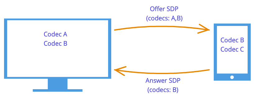
 Figure 7: Codec negotiation
Candidates (Ice candidate)
Technology WebRTC trying to confuse us with his new methodology. When establishing a connection, the address of the node with which you want to connect is not specified. Installed first logical connection, not physical, although the opposite has always been done. But this will not seem strange, if we do not forget that we use a third-party signaling mechanism.
So, the connection has already been established (logical connection), but there is no way yet for the network nodes to transmit data. It's not all that simple, but let's start simple. Let the nodes be in the same private network. As we already know, they can easily connect to each other through their internal IP addresses (or maybe some other, if not used TCP/IP).
Through some callback'and WebRTC tells us Ice candidate objects. They also come in textual form and just like with session descriptors, they just need to be sent through the signaling mechanism. If the session descriptor contained information about our settings at the camera and microphone level, then the candidates contain information about our location on the network. Pass them to another node, and he will be able to physically connect to us, and since he already has a session descriptor, he can logically connect and the data will “flow”. If he does not forget to send us his candidate object, that is, information about where he is in the network, then we will be able to connect with him. We note here one more difference from the classical client-server interaction. Communication with the HTTP server occurs according to the request-response scheme, the client sends data to the server, which processes it and sends it via address specified in the request packet. AT WebRTC need to know two addresses and connect them on both sides.
The difference from session handles is that only remote candidates need to be set. Editing is prohibited here and cannot bring any benefit. In some implementations WebRTC candidates need only be set after the session handles have been set.
And why was there only one session descriptor, but there can be many candidates? Because the location in the network can be determined not only by its internal IP address, but also the external address of the router, and not necessarily one, as well as the addresses TURN servers. The rest of the paragraph will be devoted to a detailed discussion of candidates and how to connect nodes from different private networks.
So, two nodes are in the same network (Figure 8). How to identify them? By using IP addresses. No other way. True, you can still use different transports ( TCP and UDP) and different ports. This is the information that is contained in the candidate object - IP, PORT, TRANSPORT and some other. Let, for example, use UDP transport and 531 port.
Figure 8: Two nodes are on the same network
Then if we are in a node p1, then WebRTC will give us such a candidate object - . This is not an exact format, but only a diagram. If we're in a knot p2, then the candidate is . Through the signaling mechanism p1 will receive a candidate p2(i.e. node location p2, namely his IP and PORT). Then p1 can connect with p2 directly. More correct, p1 will send data to the address 10.50.150.3:531 in the hope that they will reach p2. It doesn't matter if this address belongs to a node p2 or some intermediary. The only important thing is that data will be sent through this address and can reach p2.
As long as the nodes are in the same network - everything is simple and easy - each node has only one candidate object (always meaning its own, that is, its location in the network). But there will be much more candidates when the nodes are in different networks.
Let's move on to a more complicated case. One node will be behind the router (more precisely, behind NAT), and the second node will be in the same network with this router (for example, on the Internet) (Figure 9).
Figure 9: One host behind NAT, another not
This case has a particular solution to the problem, which we now consider. A home router usually contains a table NAT. This is a special mechanism designed to allow nodes within the router's private network to access, for example, websites.
Let's assume that the web server is directly connected to the Internet, that is, it has a public IP* address. Let it be a knot p2. Knot p1(web client) sends a request to the address 10.50.200.10 . First, the data goes to the router r1, or rather on his interior interface 192.168.0.1 . After that, the router remembers the source address (address p1) and enters it in a special table NAT, then changes the source address to its own( p1 → r1). Further, according to external interface, the router sends data directly to the web server p2. The web server processes the data, generates a response, and sends it back. Sends to the router r1, since it is he who is in the return address (the router changed the address to its own). The router receives data, looks at the table NAT and sends the data to the node p1. The router acts as an intermediary here.
But what if several nodes from the internal network access the external network at the same time? How will the router understand who to send the response back to? This problem is solved with ports. When the router replaces the host address with its own, it also replaces the port. If two nodes access the Internet, then the router replaces their source ports with various. Then, when the packet from the web server comes back to the router, the router will understand by the port to whom this packet is assigned. An example is below.
Back to Technology WebRTC, or rather, to its part that uses ICE protocol (hence Ice candidates). Knot p2 has one candidate (its location in the network - 10.50.200.10 ), and the node p1, which is located behind a router with NAT, will have two candidates - local ( 192.168.0.200 ) and router candidate ( 10.50.200.5 ). The first one is not useful, but it is nevertheless generated, since WebRTC does not yet know anything about the remote host - it may or may not be on the same network. The second candidate will come in handy, and as we already know, the port will play an important role (to get through NAT).
Table entry NAT generated only when data exits the internal network. Therefore, the node p1 must first transmit the data and only after that the data of the node p2 can get to the node p1.
On practice both nodes will be behind NAT. To create an entry in a table NAT each router, the nodes must send something to the remote node, but this time neither the first can reach the second, nor vice versa. This is due to the fact that the nodes do not know their external IP addresses, and sending data to internal addresses is meaningless.
However, if the external addresses are known, then the connection will be easily established. If the first node sends data to the router of the second node, then the router will ignore them, since its table NAT while empty. However, in the router of the first node in the table NAT there was a need for a record. If now the second node sends data to the router of the first node, then the router will successfully transmit them to the first node. Now the table NAT the second router has the data you need.
The problem is that in order to know your external IP address, you need a node located on a common network. To solve this problem, additional servers are used that are directly connected to the Internet. With their help, the treasured records in the table are also created. NAT.
STUN and TURN servers
At initialization WebRTC available STUN and TURN servers, which we will refer to as ICE servers. If the servers are not specified, then only nodes in the same network (connected to it without NAT). It should be noted right away that for 3g-networks must be used TURN servers.
STUN server is simply a server on the Internet that returns a return address, that is, the address of the sender's host. The node behind the router accesses STUN server to go through NAT. The package that came to STUN server, contains the source address - the address of the router, that is, the external address of our node. This adress STUN server and sends back. Thus, the node gets its external IP address and port through which it is accessible from the network. Further, WebRTC using this address creates an additional candidate (external router address and port). Now in the table NAT the router has an entry that passes packets sent to the router on the required port to our node.
Let's look at this process with an example.
Example (STUN server operation)
STUN the server will be denoted by s1. Router, as before, through r1, and the node through p1. You will also need to follow the table NAT- let's denote it as r1_nat. Moreover, this table usually contains many entries from different subnet nodes - they will not be given.
So, at the beginning we have an empty table r1_nat.
Table 2: Packet header
Knot p1 sends this packet to the router r1(no matter how, different technologies can be used in different subnets). The router needs to make a substitution of the source address src IP, since the address specified in the packet is certainly not suitable for the external subnet, moreover, addresses from this range are reserved, and not a single address on the Internet has such an address. The router makes a substitution in the packet and creates a new entry in its table r1_nat. To do this, he needs to come up with a port number. Recall that, since several nodes within a subnet can access an external network, then in the table NAT additional information must be stored so that the router can determine which of these several hosts the return packet from the server is destined for. Let the router come up with a port 888 .
Changed package header:
Table 4: NAT table updated with a new entry
Here IP the address and port for the subnet are exactly the same as the original packet. Indeed, on postback, we must have a way to completely restore them. IP the address for the external network is the address of the router, and the port has changed to the one invented by the router.
The real port to which the node p1 accepts a connection - this, of course, 35777 , but the server sends data to fictitious port 888 , which will be changed by the router to the real 35777 .
So, the router changed the source address and port in the packet header and added an entry to the table NAT. Now the packet is sent over the network to the server, that is, the node s1. at the entrance, s1 has this package:
| src IP | Src PORT | Dest IP | DEST PORT |
|---|---|---|---|
| 10.50.200.5 | 888 | 12.62.100.200 | 6000 |
Table 5: STUN server received a packet
Total STUN the server knows that it received a packet from the address 10.50.200.5:888 . Now the server sends this address back. It is worth stopping here and revisiting what we have just considered. The tables above are part of header package, not from it at all content. We did not talk about the content, since it is not so important - it is somehow described in the protocol STUN. Now we will consider in addition to the title also the content. It will be simple and contain the address of the router - 10.50.200.5:888 although we took it from header package. This is not often done, usually protocols do not care about the information about the addresses of the nodes, it is only important that the packets are delivered to their destination. Here we consider a protocol that establishes a path between two nodes.
So now we have a second batch going in the opposite direction:
Table 7: STUN server sends a packet with this content
Next, the packet travels through the network until it reaches the external interface of the router r1. The router understands that the package is not intended for him. How does he understand it? This can only be found by the port. Port 888 he does not use for his personal purposes, but uses for the mechanism NAT. Therefore, the router looks into this table. Looks at the column External PORT and looks for a string that matches DEST PORT from the incoming package, that is 888 .
| internal IP | Internal PORT | external IP | External PORT |
|---|---|---|---|
| 192.168.0.200 | 35777 | 10.50.200.5 | 888 |
Table 8: NAT table
We are lucky that such a line exists. If it were not lucky, then the packet would simply be discarded. Now you need to understand which of the subnet nodes should send this packet. Let's not rush, let's recap the importance of ports in this mechanism. At the same time, two nodes on the subnet could send requests to the external network. Then, if for the first node the router came up with a port 888 , then for the second he would come up with a port 889 . Suppose that this happened, that is, the table r1_nat looks like that:
Table 10: Router spoofing receiver address
| src IP | Src PORT | Dest IP | DEST PORT |
|---|---|---|---|
| 12.62.100.200 | 6000 | 192.168.0.200 | 35777 |
Table 11: The router changed the receiver address
The packet successfully arrives at the node p1 and by looking at the contents of the packet, the node learns about its external IP address, that is, the address of the router in the external network. It also knows the port that the router passes through NAT.
What's next? What's the use of all this? Benefit is an entry in the table r1_nat. If now anyone will send to the router r1 port package 888 , then the router will forward this packet to the host p1. Thus, a small narrow passage was created to the hidden node p1.
From the example above, you can get some idea of how it works. NAT and essence STUN server. In general, the mechanism ICE and STUN/TURN servers are just aimed at overcoming restrictions NAT.
There can be more than one router between the node and the server, but several. In this case, the node will receive the address of the router that is the first to enter the same network as the server. In other words, we get the address of the router connected to STUN server. For p2p communication is just what we need, if we do not forget the fact that in each router the line we need will be added to the table NAT. So the way back will be just as smooth again.
TURN server is improved STUN server. From this it follows immediately that any TURN the server can work and how STUN server. However, there are also benefits. If a p2p communication is not possible (as in 3g networks), then the server switches to repeater mode ( relay), that is, it works as an intermediary. Of course, about any p2p then it is not a question, but outside the framework of the mechanism ICE the nodes think they are communicating directly.
In what cases is it necessary TURN server? Why is not enough STUN servers? The fact is that there are several types NAT. They replace the same IP address and port, but some of them have built-in additional protection against “falsification”. For example, in symmetrical table NAT 2 more parameters are saved - IP and port of the remote host. A packet from the external network passes through NAT to the internal network only if the source address and port match those recorded in the table. Therefore, the focus STUN server fails - table NAT stores address and port STUN server and when the router receives a packet from WebRTC interlocutor, he discards him, as he is “falsified”. He didn't come from STUN server.
In this way TURN a server is needed when both interlocutors are behind symmetrical NAT(each for his own).
Brief summary
Here are some statements about entities WebRTC which must always be kept in mind. They are described in detail above. If any of the statements do not seem completely clear to you, reread the relevant paragraphs.
- media stream
- Video and audio data is packed into media streams
- Media streams synchronize the media tracks that make up
- Different media streams are out of sync
- Media streams can be local and remote, a camera and a microphone are usually connected to the local one, remote ones receive data from the network in encrypted form
- There are two types of media tracks - for video and for audio.
- Media tracks have the ability to turn on/off
- Media tracks are made up of media channels
- Media tracks synchronize the media channels that make up
- Media streams and media tracks have labels by which they can be distinguished
- Session handle
- The session descriptor is used to logically connect two network nodes
- The session descriptor stores information about the available encoding methods for video and audio data.
- WebRTC uses an external signaling mechanism - the task of forwarding session descriptors ( sdp) falls on the application
- The logical connection mechanism consists of two stages - a proposal ( offer) and response ( answer)
- Session descriptor generation is not possible without using a local media stream in case of an offer ( offer) and is not possible without using a remote session descriptor in case of a response ( answer)
- The resulting descriptor must be given to the implementation WebRTC, and it doesn't matter if this handle is obtained remotely or locally from the same implementation WebRTC
- It is possible to slightly edit the session descriptor
- Candidates
- Candidate ( Ice candidate) is the address of the node in the network
- The node address can be your own, or it can be the address of a router or TURN servers
- There are always many candidates
- The candidate consists of IP address, port and type of transport ( TCP or UDP)
- Candidates are used to establish a physical connection between two nodes in a network
- Candidates also need to be sent through the signaling mechanism
- Candidates also need to pass implementations WebRTC, but only remote
- In some implementations WebRTC Candidates can only be passed after the session descriptor has been set
- STUN/TURN/ICE/NAT
- NAT– a mechanism for providing access to an external network
- Home routers support a special table NAT
- The router replaces the addresses in the packets - the source address with its own, if the packet goes to the external network, and the destination address with the host address in the internal network, if the packet came from the external network
- To provide multi-channel access to an external network NAT uses ports
- ICE- bypass mechanism NAT
- STUN and TURN servers - helper servers for bypassing NAT
- STUN the server allows you to create the necessary entries in the table NAT, and also returns the external address of the node
- TURN server generalizes STUN mechanism and makes it always work
- In the worst cases TURN the server is used as an intermediary ( relay), that is p2p turns into a client-server-client connection.
European Internet users are divided into two parts: according to a survey by the Institute for Public Opinion Analysis in Allenbach (Germany), Skype, chat and instant messaging systems have become an integral part of everyday life for 16.5 million adults and children, 9 million use these services from case by case, and 28 million do not touch them.
The situation may change, since now Firefox is integrated real time communication technology (WebRTC), as well as the client himself. Starting an audio and video chat is now no more difficult than opening a website. Services such as Facebook and Skype, on the other hand, rely on solutions using a separate client and creating an account.
WebRTC is not only easy to use. This method even allows you to set direct connection between two browsers. In this way, audio and video data does not pass through a server where congestion can occur or where the administrator is not particularly sensitive to privacy or data protection. With a direct connection, WebRTC does not require registration or an account with any service.

To start a conversation, you only need to follow the link. Communication remains private because the data stream is encrypted. Real-time communication through the browser, Google began to actively engage in back in 2011, when it published the source code of its WebRTC implementation.
Shortly thereafter, Chrome and Firefox received their own WebRTC engines. Currently, their mobile versions are equipped with both this technology and the WebView 3.6 engine installed with Android 5.0, which is used by applications.
For real-time communication, the appropriate JavaScript interfaces must be implemented in the web viewer. With GetUserMedia, the software enables capture from audio and video sources, i.e. webcam and microphone. RTCPeerConnection is responsible for establishing the connection, as well as for the communication itself.
In parallel with browser integration, the World Wide Web Consortium (W3C) working group has been pushing the WebRTC standardization process. It should be completed in 2015.
WebRTC is content with little
Using the WebRTC service does not require many resources, since the server only connects the buddies. Establishing a connection is also not particularly difficult. First, the browser signals the WebRTC server that it plans to initiate a call. It receives an HTTPS link from the server - the connection is encrypted. The user sends this link to his interlocutor. The browser then asks the user for permission to access the webcam and microphone.
To establish a direct streaming connection with the other party, the browser receives its IP address and configuration data from the WebRTC service. The buddy's web browser does the same.
In order for the streaming connection to function smoothly and in good quality, three engines work in the browser. Two of them optimize and compress audio and video data, the third is responsible for their transportation. It sends data via SRTP protocol(Secure Real-time Transport Protocol), which allows real-time encrypted streaming.
If a direct connection fails, WebRTC looks for another path. For example, this happens when the network settings prevent the STUN server from being able to report the IP address. The WebRTC standard stipulates that in this case the conversation will take place, but with the intermediate inclusion of the TURN server (Traversal Using Relays around NAT). So, on the netscan.co website, you can check if WebRTC is implemented on your computer and with your access to the Web.
How the connection is made
 First you need to register a conversation (1). The WebRTC service provides a link that needs to be sent to the interlocutor. The browser, using the STUNserver, finds out its own IP address (2), sends it to the service and receives the IP of the partner to establish a direct connection (3). If STUN fails, the conversation is redirected using the TURNserver (4).
Communication using WebRTC technology in the browser is launched using JavaScript code. After that, three engines are responsible for communication: the voice and video engines collect multimedia data from the webcam and microphone, and the transport engine combines the information and sends the stream in encrypted form using the Secure Real-time Protocol (SRTP).
Which browsers work with WebRTC
Chrome and Firefox are equipped with a WebRTC engine that uses services such as talky.io. The Mozilla browser can work directly with its own client.

Google and Mozilla continue to develop the idea of real-time communication: Chrome can host a WebRTC conference with multiple participants, and the new Hello client in Firefox is developed with the help of a subsidiary of telecommunications giant Telefonica. Apple remains on the sidelines for now, you should not expect WebRTC in Safari yet. However, there are plenty of alternative iOS apps and plugins for Safari.
Microsoft is taking a slightly different course. As the owner of the competitive Skype service, this company is not going to capitulate to WebRTC so easily. Instead, Microsoft is developing a technology called ORTC (Object Real-Time Communications) for Internet Explorer.
Differences from WebRTC, such as different codecs and protocols for establishing contact with the server, are minor and over time, most likely, will become in addition to the WebRTC standard, which will include these differences. Thus, only Apple remains behind - as usual.
A photo: manufacturing companies; goodluz/Photolia.com
Technologies for calling from the browser are many years old: Java, ActiveX, Adobe Flash... In the last few years, it has become clear that plug-ins and left virtual machines do not shine with convenience (why should I install anything at all?) and, most importantly, security . What to do? There is an exit!
Until recently, several protocols have been used on IP networks for IP telephony or video: SIP, the most common protocol coming off the scene, H.323 and MGCP, Jabber/Jingle (used in Gtalk), the semi-open Adobe RTMP* and, of course, the closed Skype. The WebRTC project, initiated by Google, is trying to turn the world of IP and web telephony around by making all softphones, including Skype, obsolete. WebRTC does not just implement all communication capabilities directly inside the browser, which is now installed on almost every device, but simultaneously tries to solve a more general task of communications between browser users (exchange of various data, screen broadcasting, collaboration with documents, and much more).
WebRTC by a web developer
From a web developer's point of view, WebRTC consists of two main parts:
- management of media streams from local resources (camera, microphone, or local computer screen) is implemented by the navigator.getUserMedia method, which returns a MediaStream object;
- peer-to-peer communications between devices that generate media streams, including the definition of communication methods and their direct transmission - RTCPeerConnection objects (for sending and receiving audio and video streams) and RTCDataChannel (for sending and receiving data from the browser).
What do we do?
We will figure out how to organize the simplest multiplayer video chat between browsers based on WebRTC using web sockets. Let's start experimenting in Chrome/Chromium, as the most advanced browsers in terms of WebRTC, although Firefox 22, released on June 24, almost caught up with them. It must be said that the standard has not yet been adopted, and the API may change from version to version. All examples were tested in Chromium 28. For simplicity, we will not monitor the cleanliness of the code and cross-browser compatibility.
media stream
The first and simplest WebRTC component is MediaStream. It provides the browser with access to media streams from the camera and microphone of the local computer. In Chrome, this requires calling the navigator.webkitGetUserMedia() function (because the standard is not finalized yet, all functions come with a prefix, and in Firefox the same function is called navigator.mozGetUserMedia()). When it is called, the user will be prompted to allow access to the camera and microphone. It will be possible to continue the call only after the user gives his consent. The parameters of the required media stream and two callback functions are passed as parameters to this function: the first one will be called in case of successful access to the camera/microphone, the second one - in case of an error. First, let's create an HTML file rtctest1.html with a button and an element
Microsoft CU-RTC-Web
Microsoft wouldn't be Microsoft if, in response to Google's initiative, it didn't immediately release its own incompatible custom variant called CU-RTC-Web (html5labs.interoperabilitybridges.com/cu-rtc-web/cu-rtc-web.htm). Although the share of IE, already small, continues to decline, the number of Skype users gives Microsoft hope to push Google, and it can be assumed that this standard will be used in the browser version of Skype. The Google standard focuses primarily on browser-to-browser communication; at the same time, the bulk of voice traffic still remains in the conventional telephone network, and gateways between it and IP networks are needed not only for ease of use or faster distribution, but also as a means of monetization that will allow more players to develop them . The appearance of another standard can not only lead to an unpleasant need for developers to support two incompatible technologies at once, but also in the future give the user a wider choice of possible functionality and available technical solutions. Wait and see.
Enable local thread
Inside tags In our HTML file, let's declare a global variable for the media stream:
VarlocalStream = null;
The first parameter to the getUserMedia method is to specify the parameters of the requested media stream - for example, simply enable audio or video:
Var streamConstraints = ( "audio": true, "video": true ); // Request access to both audio and video
Or specify additional options:
Var streamConstraints = ( "audio": true, "video": ( "mandatory": ( "maxWidth": "320", "maxHeight": "240", "maxFrameRate": "5" ), "optional": ) );
The second parameter to the getUserMedia method is to pass a callback function that will be called if it is successful:
Function getUserMedia_success(stream) ( console.log("getUserMedia_success():", stream); localVideo1.src = URL.createObjectURL(stream); // Attach media stream to HTML element
The third parameter is a callback function, an error handler that will be called in case of an error.
Function getUserMedia_error(error) ( console.log("getUserMedia_error():", error); )
The actual call to the getUserMedia method - requesting access to the microphone and camera when the first button is pressed
Function getUserMedia_click() ( console.log("getUserMedia_click()"); navigator.webkitGetUserMedia(streamConstraints, getUserMedia_success, getUserMedia_error); )
It is not possible to access the media stream from a file opened locally. If we try to do this, we get an error:
NavigatorUserMediaError (code: 1, PERMISSION_DENIED: 1)"
Let's upload the resulting file to the server, open it in the browser and, in response to the request that appears, allow access to the camera and microphone.
You can select which devices Chrome will access in Settings, Show advanced settings link, Privacy section, Content button. In Firefox and Opera browsers, devices are selected from the drop-down list directly when access is granted.
When using the HTTP protocol, permission will be requested each time a media stream is accessed after the page is loaded. Switching to HTTPS will allow you to display the request once, only on the very first access to the media stream.
Pay attention to the pulsating circle in the icon on the tab and the camera icon on the right side of the address bar:
RTCMediaConnection
RTCMediaConnection - an object designed to establish and transfer media streams over the network between participants. In addition, this object is responsible for generating a media session description (SDP), obtaining information about ICE candidates for passing through NAT or firewalls (local and using STUN), and interacting with the TURN server. Each participant must have one RTCMediaConnection per connection. Media streams are transmitted over the encrypted SRTP protocol.
TURN servers
There are three types of ICE candidates: host, srflx, and relay. Host contains information obtained locally, srflx is what the host looks like to an external server (STUN), and relay is information for proxying traffic through the TURN server. If our node is behind a NAT, then host candidates will contain local addresses and will be useless, srflx candidates will only help with certain types of NAT and relay will be the last hope to pass traffic through an intermediate server.
An example of an ICE candidate of type host, with address 192.168.1.37 and port udp/34022:
A=candidate:337499441 2 udp 2113937151 192.168.1.37 34022 typ host generation 0
General format for specifying STUN/TURN servers:
Var servers = ( "iceServers": [ ( "url": "stun:stun.stunprotocol.org:3478" ), ( "url": "turn: [email protected]:port", "credential": "password" ) ]);
There are many public STUN servers on the Internet. A large list, for example, is . Unfortunately, they solve too few of the problems. There are practically no public TURN servers, unlike STUN. This is due to the fact that the TURN server passes media streams through itself, which can significantly load both the network channel and the server itself. Therefore, the easiest way to connect to TURN servers is to install it yourself (obviously, you will need a public IP). Of all the servers, in my opinion, the best is rfc5766-turn-server . Under it, there is even a ready-made image for Amazon EC2.
With TURN, not everything is as good as we would like, but active development is underway, and I would like to hope that after some time WebRTC, if it does not catch up with Skype in terms of the quality of passing through address translation (NAT) and firewalls, then at least noticeably come closer.
RTCMediaConnection needs an additional mechanism for exchanging control information to establish a connection - although it generates this data, it does not transmit it, and transmission by other participants must be implemented separately.

The choice of transmission method is the responsibility of the developer - at least manually. As soon as the necessary data is exchanged, RTCMediaConnection will set up media streams automatically (if possible, of course).
offer-answer model
To establish and modify media streams, the offer / answer model (offer / response; described in RFC3264) and the SDP protocol (Session Description Protocol) are used. They are also used by the SIP protocol. In this model, two agents are distinguished: Offerer - the one who generates an SDP session description to create a new one or modify an existing one (Offer SDP), and Answerer - one who receives an SDP session description from another agent and responds to it with his own session description (Answer SDP). At the same time, the specification requires a higher-level protocol (for example, SIP or its own over web sockets, as in our case), which is responsible for transferring SDP between agents.
What data needs to be passed between two RTCMediaConnections so that they can successfully establish media streams:
- The first party initiating the connection forms an Offer in which it transmits an SDP data structure (the same protocol is used for the same purpose in SIP) describing the possible characteristics of the media stream that it is about to start transmitting. This data block must be transferred to the second participant. The second participant generates an Answer with his SDP and sends it to the first.
- Both the first and second participants perform the procedure for determining possible ICE candidates, with the help of which the second participant can transfer the media stream to them. As candidates are identified, information about them should be transferred to another participant.

Offer Formation
To form an Offer, we need two functions. The first one will be called in case of its successful formation. The second parameter of the createOffer() method is a callback function called in case of an error during its execution (provided that the local stream is already available).
Additionally, two event handlers are needed: onicecandidate when defining a new ICE candidate and onaddstream when connecting a media stream from the far side. Let's go back to our file. Add to HTML after lines with elements
And after the line with the element
Also, at the beginning of the JavaScript code, we will declare a global variable for RTCPeerConnection:
varpc1;
When calling the RTCPeerConnection constructor, you must specify the STUN/TURN servers. See sidebar for more details; as long as all participants are on the same network, they are not required.
var servers = null;
Options for Provisioning Offer SDP
var offerConstraints = ();
The first parameter of the createOffer() method is a callback function called upon successful formation of an Offer
Function pc1_createOffer_success(desc) ( console.log("pc1_createOffer_success(): \ndesc.sdp:\n"+desc.sdp+"desc:", desc); pc1.setLocalDescription(desc); // Set the RTCPeerConnection generated by the Offer SDP setLocalDescription method. // When the far side sends its Answer SDP, it will need to be set using the setRemoteDescription method // Until the second side is implemented, do nothing // pc2_receivedOffer(desc); )
The second parameter is a callback function that will be called in case of an error
Function pc1_createOffer_error(error)( console.log("pc1_createOffer_success_error(): error:", error); )
And we will declare a callback function that will be passed ICE candidates as they are defined:
Function pc1_onicecandidate(event)( if (event.candidate) ( console.log("pc1_onicecandidate():\n"+ event.candidate.candidate.replace("\r\n", ""), event.candidate); // Do nothing until the second side is implemented // pc2.addIceCandidate(new RTCIceCandidate(event.candidate)); ) )
As well as a callback function for adding a media stream from the far side (for the future, since we only have one RTCPeerConnection so far):
Function pc1_onaddstream(event) ( console.log("pc_onaddstream()"); remoteVideo1.src = URL.createObjectURL(event.stream); )
When you click on the “createOffer” button, create an RTCPeerConnection, set the onicecandidate and onaddstream methods, and request the formation of an Offer SDP by calling the createOffer() method:
Function createOffer_click() ( console.log("createOffer_click()"); pc1 = new webkitRTCPeerConnection(servers); // Create an RTCPeerConnection pc1.onicecandidate = pc1_onicecandidate; // Callback function to process ICE candidates pc1.onaddstream = pc1_onaddstream; // Callback function called when there is a media stream from the far side, it does not exist yet pc1.addStream(localStream); // Pass the local media stream (assuming it has already been received) pc1.createOffer(// And actually request the formation of the Offer pc1_createOffer_success , pc1_createOffer_error, offerConstraints); )
Let's save the file as rtctest2.html, put it on the server, open it in a browser and see in the console what data is generated during its operation. The second video will not appear yet, as there is only one participant. Recall that SDP is a description of the media session parameters, available codecs, media streams, and ICE candidates are possible options for connecting to this participant.
Formation of Answer SDP and exchange of ICE candidates
Both the Offer SDP and each of the ICE candidates must be passed to the other side, and there, after receiving them from the RTCPeerConnection, call the setRemoteDescription methods for the Offer SDP and addIceCandidate for each ICE candidate received from the far side; similarly in reverse for Answer SDP and remote ICE candidates. The Answer SDP itself is formed similarly to the Offer; the difference is that not the createOffer method is called, but the createAnswer method, and before this RTCPeerConnection, the setRemoteDescription method passes the Offer SDP received from the caller.
Let's add another video element to the HTML:
And a global variable for the second RTCPeerConnection under the declaration of the first one:
Varpc2;
Processing Offer and Answer SDP
Forming an Answer SDP is very similar to an Offer. In the callback function called upon successful formation of the Answer, similarly to Offer, we will give a local description and pass the received Answer SDP to the first participant:
Function pc2_createAnswer_success(desc) ( pc2.setLocalDescription(desc); console.log("pc2_createAnswer_success()", desc.sdp); pc1.setRemoteDescription(desc); )
The callback function called in case of an error while generating the Answer is completely similar to the Offer:
Function pc2_createAnswer_error(error) ( console.log("pc2_createAnswer_error():", error); )
Parameters for generating Answer SDP:
Var answerConstraints = ( "mandatory": ( "OfferToReceiveAudio":true, "OfferToReceiveVideo":true ) );
When the second participant receives an Offer, create an RTCPeerConnection and form an Answer in the same way as the Offer:
Function pc2_receivedOffer(desc) ( console.log("pc2_receiveOffer()", desc); // Create an RTCPeerConnection object for the second participant similar to the first pc2 = new webkitRTCPeerConnection(servers); pc2.onicecandidate = pc2_onicecandidate; // Set the event handler when ICE candidate pc2.onaddstream = pc_onaddstream; // When a stream appears, connect it to the HTML
In order to transfer the Offer SDP from the first participant to the second one, as part of our example, uncomment in the pc1 function createOffer success() call string:
Pc2_receivedOffer(desc);
To implement the processing of ICE candidates, uncomment in the ICE candidate readiness event handler of the first participant pc1_onicecandidate() its transmission to the second:
Pc2.addIceCandidate(new RTCIceCandidate(event.candidate));
The ICE candidate readiness event handler of the second participant is mirror-like to the first one:
Function pc2_onicecandidate(event) ( if (event.candidate) ( console.log("pc2_onicecandidate():", event.candidate.candidate); pc1.addIceCandidate(new RTCIceCandidate(event.candidate)); ) )
Callback function for adding a media stream from the first participant:
Function pc2_onaddstream(event) ( console.log("pc_onaddstream()"); remoteVideo2.src = URL.createObjectURL(event.stream); )
Terminating a connection
Let's add another button in HTML
And a function to end the connection
Function btnHangupClick() ( // Disable local video from HTML elements
Let's save it as rtctest3.html, put it on the server and open it in the browser. This example implements two-way media streaming between two RTCPeerConnections within the same browser tab. To organize the exchange of Offer and Answer SDP, ICE candidates between participants and other information through the network, it will be necessary to implement the exchange between participants using some kind of transport, in our case, web sockets, instead of a direct call to procedures.
Screen Broadcast
With the getUserMedia function, you can also capture the screen and stream as a MediaStream by specifying the following parameters:
Var mediaStreamConstraints = ( audio: false, video: ( mandatory: ( chromeMediaSource: "screen" ), optional: ) );
For successful access to the screen, several conditions must be met:
- enable screenshot flag in getUserMedia() in chrome://flags/,chrome://flags/;
- the source file must be downloaded via HTTPS (SSL origin);
- the audio stream must not be requested;
- multiple requests should not be made in the same browser tab.
Libraries for WebRTC
Although WebRTC is not yet complete, several libraries based on it have already appeared. JsSIP is designed to create browser-based softphones that work with SIP switches such as Asterisk and Camalio. PeerJS will simplify the creation of P2P networks for data exchange, and Holla will reduce the amount of development required for P2P communication from browsers.
Node.js and socket.io
In order to organize the exchange of SDP and ICE candidates between two RTCPeerConnections over the network, we use Node.js with the socket.io module.
Installing the latest stable version of Node.js (for Debian/Ubuntu) is described
$ sudo apt-get install python-software-properties python g++ make $ sudo add-apt-repository ppa:chris-lea/node.js $ sudo apt-get update $ sudo apt-get install nodejs
Installation for other operating systems is described
Let's check:
$ echo "sys=require("util"); sys.puts("Test message");" > nodetest1.js $ nodejs nodetest1.js
Using npm (Node Package Manager) install socket.io and the additional express module:
$ npm install socket.io express
Let's check it by creating a nodetest2.js file for the server side:
$ nano nodetest2.js var app = require("express")() , server = require("http").createServer(app) , io = require("socket.io").listen(server); server.listen(80); // If port 80 is free app.get("/", function (req, res) ( // When accessing the root page res.sendfile(__dirname + "/nodetest2.html"); // give the HTML file )) ; io.sockets.on("connection", function (socket) ( // On connection socket.emit("server event", ( hello: "world" )); // send message socket.on("client event", function (data) ( // and declare an event handler when a message arrives from the client console.log(data); )); ));
And nodetest2.html for the client side:
$nano nodetest2.html
Let's start the server:
$ sudo nodejs nodetest2.js
and open the page http://localhost:80 (if running locally on port 80) in a browser. If everything is successful, in the JavaScript console of the browser we will see the exchange of events between the browser and the server upon connection.
Exchange of information between RTCPeerConnection via web sockets
Client side
Let's save our main example (rtcdemo3.html) under the new name rtcdemo4.html. Include the socket.io library in the element:
And at the beginning of the JavaScript script - web socket connection:
var socket = io.connect("http://localhost");
Let's replace a direct call to the functions of another participant by sending him a message via web sockets:
Function createOffer_success(desc) ( ... // pc2_receivedOffer(desc); socket.emit("offer", desc); ... ) function pc2_createAnswer_success(desc) ( ... // pc1.setRemoteDescription(desc); socket .emit("answer", desc); ) function pc1_onicecandidate(event) ( ... // pc2.addIceCandidate(new RTCIceCandidate(event.candidate)); socket.emit("ice1", event.candidate); .. . ) function pc2_onicecandidate(event) ( ... // pc1.addIceCandidate(new RTCIceCandidate(event.candidate)); socket.emit("ice2", event.candidate); ... )
In the hangup() function, instead of directly calling the functions of the second participant, we will send a message via web sockets:
Function btnHangupClick() ( ... // remoteVideo2.src = ""; pc2.close(); pc2 = null; socket.emit("hangup", ()); )
And add message receiving handlers:
Socket.on("offer", function (data) ( console.log("socket.on("offer"):", data); pc2_receivedOffer(data); )); socket.on("answer", function (data) (e console.log("socket.on("answer"):", data); pc1.setRemoteDescription(new RTCSessionDescription(data)); )); socket.on("ice1", function (data) ( console.log("socket.on("ice1"):", data); pc2.addIceCandidate(new RTCIceCandidate(data)); )); socket.on("ice2", function (data) ( console.log("socket.on("ice2"):", data); pc1.addIceCandidate(new RTCIceCandidate(data)); )); socket.on("hangup", function (data) ( console.log("socket.on("hangup")):", data); remoteVideo2.src = ""; pc2.close(); pc2 = null; ) );
Server part
On the server side, save the nodetest2 file under the new name rtctest4.js and inside the io.sockets.on("connection", function (socket) ( ... ) function add receiving and sending client messages:
Socket.on("offer", function (data) ( // When receiving an "offer" message, // since there is only one client connection in this example, // send the message back through the same socket socket.emit("offer" , data); // If it were necessary to forward the message on all connections // except the sender: // socket.broadcast.emit("offer", data); )); socket.on("answer", function (data) ( socket.emit("answer", data); )); socket.on("ice1", function (data) ( socket.emit("ice1", data); )); socket.on("ice2", function (data) ( socket.emit("ice2", data); )); socket.on("hangup", function (data) ( socket.emit("hangup", data); ));
In addition, change the name of the HTML file:
// res.sendfile(__dirname + "/nodetest2.html"); // Send the HTML file res.sendfile(__dirname + "/rtctest4.html");
Server start:
$ sudo nodejs nodetest2.js
Despite the fact that the code of both clients runs within the same browser tab, all interaction between the participants in our example is completely carried out through the network and it is no longer difficult to “spread” the participants. However, what we did was also very simple - these technologies are good for their ease of use. Albeit sometimes deceptive. In particular, let's not forget that without STUN/TURN servers, our example will not be able to work in the presence of address translation and firewalls.
Conclusion
The resulting example is very conditional, but if we slightly universalize the event handlers so that they do not differ between the calling and called parties, instead of two objects pc1 and pc2, make an RTCPeerConnection array and implement dynamic creation and deletion of elements
It can be assumed that very soon, thanks to WebRTC, there will be a revolution not only in our understanding of voice and video communications, but also in how we perceive the Internet as a whole. WebRTC is positioned not only as a browser-to-browser call technology, but also as a real-time communication technology. Video communication, which we have analyzed, is only a small part of the possible options for its use. There are already examples of screen sharing (screen sharing), and collaboration, and even a browser-based P2P content delivery network using the RTCDataChannel.
WebRTC (Web Real Time Communications) is a standard that describes the transfer of streaming audio data, video data and content from the browser and to the browser in real time without installing plugins or other extensions. The standard allows you to turn the browser into a video conferencing terminal, just open a web page to start communication.
What is WebRTC?
In this article, we will cover everything there is to know about WebRTC technology for the average user. Let's consider the advantages and disadvantages of the project, reveal some secrets, tell you how it works, where and what WebRTC is used for.
What you need to know about WebRTC?
The evolution of video standards and technologies
Sergey Yutsaitis, Cisco, Video+Conference 2016How WebRTC works
On the client side
- The user opens a page containing an HTML5 tag
- The browser requests access to the user's webcam and microphone.
- The JavaScript code on the user page controls the connection parameters (IP addresses and ports of the WebRTC server or other WebRTC clients) to bypass NAT and Firewall.
- When receiving information about the interlocutor or about the stream with the conference mixed on the server, the browser starts negotiating the audio and video codecs used.
- The process of encoding and streaming data between WebRTC clients (in our case, between the browser and the server) begins.
On the WebRTC server side
A video server is not required for data exchange between two participants, but if you want to combine several participants in one conference, a server is required.

The video server will receive media traffic from various sources, convert it and send it to users who use WebRTC as a terminal.
The WebRTC server will also receive media traffic from WebRTC peers and pass it on to conference participants using desktop or mobile applications, if any.
Benefits of the standard
- No software installation required.
- Very high communication quality thanks to:
- Use of modern video (VP8, H.264) and audio codecs (Opus).
- Automatic adjustment of stream quality to connection conditions.
- Built-in echo and noise cancellation.
- Automatic level control of participants' microphones (AGC).
- High level of security: all connections are secure and encrypted according to the TLS and SRTP protocols.
- There is a built-in mechanism for capturing content, such as the desktop.
- Ability to implement any control interface based on HTML5 and JavaScript.
- The ability to integrate the interface with any back-end systems using WebSockets.
- An open source project - you can embed it in your product or service.
- True cross-platform: the same WebRTC application will work equally well on any operating system, desktop or mobile, provided that the browser supports WebRTC. This saves a lot of resources for software development.
Disadvantages of the standard
- To organize group audio and video conferences, a videoconferencing server is required that would mix video and audio from participants, because the browser does not know how to synchronize multiple incoming streams with each other.
- All WebRTC solutions are incompatible with each other, because the standard describes only methods for transmitting video and sound, leaving the implementation of methods for addressing subscribers, tracking their availability, exchanging messages and files, scheduling, and other things for the vendor.
- In other words, you will not be able to call from a WebRTC application of one developer to a WebRTC application of another developer.
- Mixing group conferences requires a lot of computing resources, so this type of video communication requires the purchase of a paid subscription or investment in its infrastructure, where each conference requires 1 physical core of a modern processor.
WebRTC Secrets: How Vendors Benefit From Disruptive Web Technology
Tzachi Levent-Levi, Bloggeek.me, Video+Conference 2015
WebRTC for the video conferencing market
Increase in the number of videoconferencing terminals
WebRTC technology has had a strong influence on the development of the video conferencing market. After the release of the first browsers with WebRTC support in 2013, the potential number of video conferencing terminals around the world immediately increased by 1 billion devices. In fact, each browser has become a videoconferencing terminal that is not inferior to its hardware counterparts in terms of communication quality.
Use in specialized solutions
The use of various JavaScript libraries and cloud service APIs with WebRTC support makes it easy to add video support to any web projects. In the past, real-time data transmission required developers to learn how the protocols worked and to use the work of other companies, which most often required additional licensing, which increased costs. WebRTC is already actively used in services like “Call from the site”, “Online support chat”, etc.
Ex-users of Skype for Linux
In 2014, Microsoft announced the end of support for the Skype for Linux project, which caused great annoyance among IT professionals. WebRTC technology is not tied to the operating system, but is implemented at the browser level, i.e. Linux users will be able to see WebRTC-based products and services as a full-fledged replacement for Skype.
Competition with Flash
WebRTC and HTML5 were a death blow for Flash technology, which was already going through its far from the best years. Since 2017, the leading browsers have officially stopped supporting Flash and the technology has finally disappeared from the market. But you have to give Flash credit, because it was he who created the web conferencing market and offered the technical capabilities for live communication in browsers.
WebRTC video presentations
Dmitry Odintsov, TrueConf, Video+Conference October 2017
Codecs in WebRTC
Audio codecs
To compress audio traffic in WebRTC, Opus and G.711 codecs are used.
G.711- the oldest voice codec with a high bitrate (64 kbps), which is most often used in traditional telephony systems. The main advantage is the minimal computational load due to the use of lightweight compression algorithms. The codec has a low level of compression of voice signals and does not introduce additional audio delay during communication between users.
G.711 is supported by a large number of devices. Systems that use this codec are easier to use than those based on other audio codecs (G.723, G.726, G.728, etc.). In terms of quality, G.711 received a score of 4.2 in MOS testing (a score of 4-5 is the highest and means good quality, similar to the quality of voice traffic in ISDN and even higher).
Opus is a codec with low encoding latency (from 2.5 ms to 60 ms), variable bit rate support, and high compression, which is ideal for audio streaming over variable bandwidth networks. Opus is a hybrid solution that combines the best features of SILK (Voice Compression, Human Speech Distortion Elimination) and CELT (Audio Data Encoding) codecs. The codec is freely available, developers who use it do not need to pay royalties to copyright holders. Compared to other audio codecs, Opus certainly wins in many ways. It has eclipsed quite popular low bitrate codecs such as MP3, Vorbis, AAC LC. Opus restores the "picture" of sound closer to the original than AMR-WB and Speex. This codec is the future, which is why the creators of WebRTC technology included it in the mandatory range of supported audio standards.
Video codecs
The issues of choosing a video codec for WebRTC took the developers several years, in the end they decided to use H.264 and VP8. Almost all modern browsers support both codecs. Video conferencing servers need only support one to work with WebRTC.
VP8 is a free video codec with an open license, featuring high video stream decoding speed and increased resistance to frame loss. The codec is universal, it is easy to implement it into hardware platforms, so developers of video conferencing systems often use it in their products.
Paid video codec H.264 became known much earlier than his brother. This is a codec with a high degree of compression of the video stream while maintaining high video quality. The high prevalence of this codec among hardware video conferencing systems suggests its use in the WebRTC standard.
Google and Mozilla are actively promoting the VP8 codec, while Microsoft, Apple and Cisco are actively promoting H.264 (to ensure compatibility with traditional video conferencing systems). And here a very big problem arises for developers of cloud-based WebRTC solutions, because if all participants in the conference use one browser, then it is enough to mix the conference once with one codec, and if the browsers are different and among them there is Safari / Edge, then the conference will have to be encoded twice different codecs, which will double the system requirements for the media server and, as a result, the cost of subscriptions to WebRTC services.
WebRTC API
WebRTC technology is based on three main APIs:
- (responsible for the web browser to receive audio and video signals from cameras or the user's desktop).
- RTCPeerConnection(responsible for the connection between browsers to “exchange” media data received from the camera, microphone and desktop. Also, the “duties” of this API include signal processing (cleaning it from extraneous noise, adjusting the microphone volume) and control over the audio and video codecs used) .
- RTC Data Channel(provides two-way data transfer over an established connection).
Before accessing the user's microphone and camera, the browser asks for this permission. In Google Chrome, you can pre-configure access in the "Settings" section, in Opera and Firefox, the choice of devices is carried out directly at the time of access, from the drop-down list. The permission request will always appear when using the HTTP protocol and once if using HTTPS:

RTCPeerConnection. Each browser participating in a WebRTC conference must have access to this object. Thanks to the use of RTCPeerConnection, media data from one browser to another can even pass through NAT and firewalls. To successfully transmit media streams, participants must exchange the following data using a transport such as web sockets:
- the initiating participant sends to the second participant an Offer-SDP (data structure, with the characteristics of the media stream that it will transmit);
- the second participant generates a “response” - Answer-SDP and sends it to the initiator;
- then, an exchange of ICE candidates is organized between the participants, if any are found (if the participants are behind NAT or firewalls).

After the successful completion of this exchange between the participants, the transfer of media streams (audio and video) is organized directly.
RTC Data Channel. Support for the Data Channel protocol appeared in browsers relatively recently, so this API can only be considered in cases where WebRTC is used in Mozilla Firefox 22+ and Google Chrome 26+ browsers. With it, participants can exchange text messages in the browser.
WebRTC connection
Supported desktop browsers
- Google Chrome (17+) and all browsers based on the Chromium engine;
- Mozilla Firefox (18+);
- Opera (12+);
- Safari (11+);
Supported mobile browsers for Android
- Google Chrome (28+);
- Mozilla Firefox (24+);
- Opera Mobile (12+);
- Safari (11+).
WebRTC, Microsoft and Internet Explorer
For a very long time, Microsoft was silent about WebRTC support in Internet Explorer and in its new Edge browser. The guys from Redmond don't really like to put technology in the hands of users that they don't control, that's the kind of policy. But gradually things got off the ground, because. It was no longer possible to ignore WebRTC, and the ORTC project, derived from the WebRTC standard, was announced.
According to the developers, ORTC is an extension of the WebRTC standard with an improved set of APIs based on JavaScript and HTML5, which, translated into ordinary language, means that everything will be the same, only Microsoft, not Google, will control the standard and its development. The set of codecs has been expanded with support for H.264 and some G.7XX series audio codecs used in telephony and hardware video conferencing systems. Perhaps there will be built-in support for RDP (for transferring content) and messaging. By the way, Internet Explorer users are out of luck, ORTC support will only be in Edge. And, of course, such a set of protocols and codecs fits in with Skype for Business with little blood, which opens up even more business applications for WebRTC.
WebRTC is a browser-provided API that allows you to organize a P2P connection and transfer data directly between browsers. There are quite a few tutorials on the Internet on how to write your own video chat using WebRTC. For example, here is an article on Habré. However, they are all limited to connecting two clients. In this article, I will try to talk about how to organize a connection and exchange of messages between three or more users using WebRTC.
The RTCPeerConnection interface is a peer-to-peer connection between two browsers. To connect three or more users, we will have to organize a mesh network (a network in which each node is connected to all other nodes).
We will use the following scheme:
- When opening the page, we check the presence of the room ID in location.hash
- If the room ID is not specified, generate a new one
- We send a signaling server "a message that we want to join the specified room
- The signaling server sends a new user notification to other clients in this room
- Clients who are already in the room send an SDP offer to the newcomer
- The newcomer responds to the offer "s
0. Signaling server
As you know, although WebRTC provides the possibility of P2P connection between browsers, it still requires an additional transport for exchanging service messages. In this example, the transport is a WebSocket server written in Node.JS using socket.io:
var socket_io = require("socket.io"); module.exports = function (server) ( var users = (); var io = socket_io(server); io.on("connection", function(socket) ( // Want a new user to join the room socket.on("room ", function(message) ( var json = JSON. parse(message); // Add the socket to the list of users users = socket; if (socket.room !== undefined) ( // If the socket is already in some room , leave it socket.leave(socket.room); ) // Enter the requested room socket.room = json.room; socket.join(socket.room); socket.user_id = json.id; // Send to other clients this room has a message about joining a new participant socket.broadcast.to(socket.room).emit("new", json.id); )); // WebRTC related message (SDP offer, SDP answer or ICE candidate) socket.on("webrtc", function(message) ( var json = JSON.parse(message); if (json.to !== undefined && users !== undefined) ( // If the message has a recipient and this recipient known to the server, send a message only to him... users.emit("webrtc", message); ) else ( // ...otherwise consider the message as a broadcast socket.broadcast.to(socket.room).emit("webrtc", message); ) )); // Someone disconnected socket.on("disconnect", function() ( // When a client disconnects, notify others socket.broadcast.to(socket.room).emit("leave", socket.user_id); delete users; )); )); );
1. index.html
The source code for the page itself is quite simple. I deliberately did not pay attention to layout and other beautiful things, since this article is not about that. If someone wants to make her beautiful, it will not be difficult.
2.main.js
2.0. Getting links to page elements and WebRTC interfaces
var chatlog = document.getElementById("chatlog"); var message = document.getElementById("message"); var connection_num = document.getElementById("connection_num"); var room_link = document.getElementById("room_link");We still have to use browser prefixes to access WebRTC interfaces.
Var PeerConnection = window.mozRTCPeerConnection || window.webkitRTCPeerConnection; var SessionDescription = window.mozRTCSessionDescription || window.RTCSessionDescription; var IceCandidate = window.mozRTCIceCandidate || window.RTCIceCandidate;
2.1. Determining the room ID
Here we need a function to generate a unique room and user ID. We will use UUID for this purpose.
Function uuid () ( var s4 = function() ( return Math.floor(Math.random() * 0x10000).toString(16); ); return s4() + s4() + "-" + s4() + "-" + s4() + "-" + s4() + "-" + s4() + s4() + s4(); )
Now let's try to extract the room ID from the address. If this is not set, we will generate a new one. We will display a link to the current room on the page, and, at the same time, we will generate an identifier for the current user.
VarROOM = location.hash.substr(1); if (!ROOM) ( ROOM = uuid(); ) room_link.innerHTML = "Link to the room"; varME = uuid();
2.2. web socket
Immediately upon opening the page, we will connect to our signaling server, send a request to enter the room and specify message handlers.
// We specify that when the message is closed, we need to send a notification to the server about this var socket = io.connect("", ("sync disconnect on unload": true)); socket.on("webrtc", socketReceived); socket.on("new", socketNewPeer); // Immediately send a request to enter the room socket.emit("room", JSON.stringify((id: ME, room: ROOM))); // Helper function for sending address messages related to WebRTC function sendViaSocket(type, message, to) ( socket.emit("webrtc", JSON.stringify((id: ME, to: to, type: type, data: message ))); )
2.3. Peer Connection Settings
Most ISPs provide Internet connectivity through NAT. Because of this, a direct connection becomes not so trivial. When creating a connection, we need to specify a list of STUN and TURN servers that the browser will try to use to bypass NAT. We will also indicate a couple of additional options for connection.
Var server = ( iceServers: [ (url: "stun:23.21.150.121"), (url: "stun:stun.l.google.com:19302"), (url: "turn:numb.viagenie.ca", credential: "your password goes here", username: " [email protected]") ] ); var options = ( optional: [ (DtlsSrtpKeyAgreement: true), // required for connection between Chrome and Firefox (RtpDataChannels: true) // required in Firefox to use the DataChannels API ] )
2.4. Connecting a new user
When a new peer is added to the room, the server sends us a message new. According to the message handlers above, the function will be called socketNewPeer.
var peers = (); function socketNewPeer(data) ( peers = (candidateCache: ); // Create a new connection var pc = new PeerConnection(server, options); // Initialize it initConnection(pc, data, "offer"); // Store the peer in the list peers peers.connection = pc; // Create a DataChannel through which messages will be exchanged var channel = pc.createDataChannel("mychannel", ()); channel.owner = data; peers.channel = channel; // Install event handlers bindEvents(channel); // Create an SDP offer pc.createOffer(function(offer) ( pc.setLocalDescription(offer); )); ) function initConnection(pc, id, sdpType) ( pc.onicecandidate = function (event) ( if (event.candidate) ( // When a new ICE candidate is found, add it to the list for further sending peers.candidateCache.push(event.candidate); ) else ( // When the discovery of candidates is completed, the handler will be called again, but without candidate // In this case, we send the peer an SDP offer first, or SDP's answer (depending on function parameter)... sendViaSocket(sdpType, pc.localDescription, id); // ...and then all previously found ICE candidates for (var i = 0; i< peers.candidateCache.length; i++) { sendViaSocket("candidate", peers.candidateCache[i], id); } } } pc.oniceconnectionstatechange = function (event) { if (pc.iceConnectionState == "disconnected") { connection_num.innerText = parseInt(connection_num.innerText) - 1; delete peers; } } } function bindEvents (channel) { channel.onopen = function () { connection_num.innerText = parseInt(connection_num.innerText) + 1; }; channel.onmessage = function (e) { chatlog.innerHTML += "
2.5. SDP offer, SDP answer, ICE candidate
When one of these messages is received, we call the corresponding message handler.
Function socketReceived(data) ( var json = JSON.parse(data); switch (json.type) ( case "candidate": remoteCandidateReceived(json.id, json.data); break; case "offer": remoteOfferReceived(json. id, json.data); break; case "answer": remoteAnswerReceived(json.id, json.data); break; ) )
2.5.0 SDP offer
function remoteOfferReceived(id, data) ( createConnection(id); var pc = peers.connection; pc.setRemoteDescription(new SessionDescription(data)); pc.createAnswer(function(answer) ( pc.setLocalDescription(answer); )); ) function createConnection(id) ( if (peers === undefined) ( peers = (candidateCache: ); var pc = new PeerConnection(server, options); initConnection(pc, id, "answer"); peers.connection = pc ; pc.ondatachannel = function(e) ( peers.channel = e.channel; peers.channel.owner = id; bindEvents(peers.channel); ) ) )2.5.1 SDP answers
function remoteAnswerReceived(id, data) ( var pc = peers.connection; pc.setRemoteDescription(new SessionDescription(data)); )2.5.2 ICE candidate
function remoteCandidateReceived(id, data) ( createConnection(id); var pc = peers.connection; pc.addIceCandidate(new IceCandidate(data)); )2.6. Sending a message
By pressing the button send function is called sendMessage. All it does is go through the list of peers and try to send the specified message to everyone.


")


