They have always been important elements of any electronic devices. These devices are used in amplifiers, as well as receivers. The main function of power supplies is considered to be the reduction of the limiting voltage that comes from the network. The first models appeared only after the invention of the AC coil.
Additionally, the development of power supplies was influenced by the introduction of transformers into the device circuit. A feature of pulse models is that they use rectifiers. Thus, voltage stabilization in the network is carried out in a slightly different way than in conventional devices where a converter is used.
Power supply device
If we consider a conventional power supply that is used in radio receivers, then it consists of a frequency transformer, a transistor, and also several diodes. Additionally, there is a choke in the circuit. Capacitors are installed with different capacities and can vary greatly in parameters. Rectifiers are used, as a rule, of a capacitor type. They belong to the category of high voltage.
Operation of modern blocks
Initially, the voltage is supplied to the bridge rectifier. At this stage, the peak current limiter is activated. This is necessary so that the fuse in the power supply does not burn out. Further, the current passes through the circuit through special filters, where it is converted. Several capacitors are needed to charge the resistors. The node starts up only after the breakdown of the dinistor. Then the transistor is unlocked in the power supply. This makes it possible to significantly reduce self-oscillations.
When voltage generation occurs, the diodes in the circuit are activated. They are interconnected by means of cathodes. The negative potential in the system makes it possible to lock the dinistor. Facilitation of starting the rectifier is carried out after the transistor is turned off. Additionally provided To prevent saturation of the transistors, there are two fuses. They work in the circuit only after a breakdown. To start the feedback, a transformer is required. It is fed by pulse diodes in the power supply. At the output, alternating current passes through capacitors.

Features of laboratory blocks
The principle of operation of switching power supplies of this type is based on active current conversion. There is one bridge rectifier in the standard circuit. In order to remove all interference, filters are used at the beginning, as well as at the end of the circuit. Capacitors switching laboratory power supply has the usual. Saturation of transistors occurs gradually, and this affects the diodes positively. Voltage regulation in many models is provided. The protection system is designed to save blocks from short circuits. Cables for them are usually used non-modular series. In this case, the power of the model can reach up to 500 watts.
The power supply connectors in the system are most often installed of the ATX 20 type. To cool the unit, a fan is mounted in the case. The speed of rotation of the blades must be regulated in this case. The laboratory-type unit must be able to withstand the maximum load at a level of 23 A. At the same time, the resistance parameter is maintained on average at around 3 ohms. The limiting frequency that the switching laboratory power supply has is 5 Hz.

How to repair devices?
Most often, power supplies suffer due to blown fuses. They are located next to the capacitors. Start repairing switching power supplies by removing the protective cover. Next, it is important to examine the integrity of the microcircuit. If defects are not visible on it, it can be checked with a tester. To remove the fuses, you must first disconnect the capacitors. After that, they can be removed without problems.
To check the integrity of this device, inspect its base. Blown fuses at the bottom have a dark spot, which indicates damage to the module. To replace this element, you need to pay attention to its marking. Then, in the radio electronics store, you can purchase a similar product. The fuse is installed only after the condensates have been fixed. Another common problem in power supplies is considered to be malfunctions with transformers. They are boxes in which coils are installed.
When the voltage on the device is very large, they do not withstand. As a result, the integrity of the winding is broken. It is impossible to repair switching power supplies with such a breakdown. In this case, the transformer, like the fuse, can only be replaced.
Network power supplies
The principle of operation of network-type switching power supplies is based on a low-frequency reduction in the amplitude of interference. This is due to the use of high voltage diodes. Thus, it is more efficient to control the limiting frequency. Additionally, it should be noted that transistors are used in medium power. The load on the fuses is minimal.
Resistors in the standard circuit are used quite rarely. This is largely due to the fact that the capacitor is able to participate in the conversion of current. The main problem of this type of power supply is the electromagnetic field. If capacitors are used with low capacitance, then the transformer is at risk. In this case, you should be very careful about the power of the device. The network switching power supply has peak current limiters, and they are located immediately above the rectifiers. Their main task is to control the operating frequency to stabilize the amplitude.
Diodes in this system partially perform the functions of fuses. Only transistors are used to drive the rectifier. The locking process, in turn, is necessary to activate the filters. Capacitors can also be used in the separation type in the system. In this case, the start of the transformer will be much faster.

Application of microcircuits
Microcircuits in power supplies are used in a variety of ways. In this situation, much depends on the number of active elements. If more than two diodes are used, then the board must be designed for input and output filters. Transformers are also produced in different capacities, and they differ quite a lot in size.
You can do soldering microcircuits yourself. In this case, you need to calculate the limiting resistance of the resistors, taking into account the power of the device. To create an adjustable model, special blocks are used. This type of system is made with double tracks. Ripple inside the board will be much faster.
Benefits of Regulated Power Supplies
The principle of operation of switching power supplies with regulators is to use a special controller. This element in the circuit can change the bandwidth of transistors. Thus, the limiting frequency at the input and at the output is significantly different. You can configure the switching power supply in different ways. Voltage regulation is carried out taking into account the type of transformer. To cool the device using conventional coolers. The problem with these devices is usually excess current. In order to solve it, protective filters are used.
The power of devices on average fluctuates around 300 watts. Cables in the system are used only non-modular. Thus, short circuits can be avoided. Power supply connectors for connecting devices are usually installed in the ATX 14 series. The standard model has two outputs. Rectifiers are used with high voltage. They are able to withstand resistance at the level of 3 ohms. In turn, the pulse regulated power supply accepts up to 12 A maximum load.

Operation of 12 volt blocks
Pulse includes two diodes. In this case, filters are installed with a small capacity. In this case, the pulsation process is extremely slow. The average frequency fluctuates around 2 Hz. The efficiency of many models does not exceed 78%. These blocks also differ in their compactness. This is due to the fact that transformers are installed with low power. They do not need refrigeration.
The 12V switching power supply circuit additionally implies the use of resistors marked P23. They can withstand only 2 ohms of resistance, but this power is enough for a device. A 12V switching power supply is used most often for lamps.
How does the TV box work?
The principle of operation of switching power supplies of this type is the use of film filters. These devices are able to cope with interference of various amplitudes. The choke winding is synthetic. Thus, the protection of important nodes is provided with high quality. All gaskets in the power supply are insulated on all sides.
The transformer, in turn, has a separate cooler for cooling. For ease of use, it is usually installed silently. The temperature limit of these devices can withstand up to 60 degrees. The switching power supply of TVs supports the operating frequency at 33 Hz. At sub-zero temperatures, these devices can also be used, but much in this situation depends on the type of condensates used and the cross section of the magnetic circuit.
Models of devices for 24 volts
In models for 24 volts, low-frequency rectifiers are used. Only two diodes can successfully cope with interference. The efficiency of such devices can reach up to 60%. Regulators on power supplies are installed quite rarely. The operating frequency of the models does not exceed 23 Hz on average. Resistance resistors can only withstand 2 ohms. Transistors in models are installed with the marking PR2.
Resistors are not used in the circuit to stabilize the voltage. Filters switching power supply 24V has a capacitor type. In some cases, you can find dividing species. They are necessary to limit the limiting frequency of the current. Dinistors are rarely used to quickly start a rectifier. The negative potential of the device is removed using the cathode. At the output, the current is stabilized by locking the rectifier.

Power supply on the DA1 diagram
Power supplies of this type differ from other devices in that they are able to withstand heavy loads. There is only one capacitor in the standard circuit. For the normal operation of the power supply, the regulator is used. The controller is installed directly next to the resistor. Diodes in the circuit can be found no more than three.
The directly reverse conversion process begins in the dinistor. To start the unlocking mechanism, a special throttle is provided in the system. Waves with large amplitude are damped at the capacitor. It is usually installed as a separation type. Fuses in the standard circuit are rare. This is justified by the fact that the limiting temperature in the transformer does not exceed 50 degrees. Thus, the ballast choke copes with its tasks on its own.
Models of devices with DA2 chips
Chips of switching power supplies of this type, among other devices, are distinguished by increased resistance. They are mainly used for measuring instruments. An example is an oscilloscope that shows fluctuations. Voltage stabilization is very important for him. As a result, the instrument readings will be more accurate.
Many models are not equipped with regulators. Filters are mostly double-sided. At the output of the circuit, transistors are installed ordinary. All this makes it possible to withstand the maximum load at the level of 30 A. In turn, the limiting frequency indicator is at around 23 Hz.
Blocks with DA3 chips installed
This microcircuit allows you to install not only a regulator, but also a controller that monitors fluctuations in the network. The resistance transistors in the device are capable of withstanding approximately 3 ohms. A powerful switching power supply DA3 copes with a load of 4 A. You can connect fans to cool the rectifiers. As a result, the devices can be used at any temperature. Another advantage is the presence of three filters.
Two of them are installed at the input under the capacitors. One separation type filter is available at the output and stabilizes the voltage that comes from the resistor. Diodes in the standard circuit can be found no more than two. However, much depends on the manufacturer, and this should be taken into account. The main problem of this type of power supply is that they are not able to cope with low-frequency interference. As a result, it is impractical to install them on measuring instruments.

How does the VD1 diode block work?
These blocks are designed to support up to three devices. Regulators in them are three-way. Cables for communication are installed only non-modular. Thus, the current conversion is fast. Rectifiers in many models are installed in the KKT2 series.
They differ in that they are able to transfer energy from the capacitor to the winding. As a result, the load from the filters is partially removed. The performance of such devices is quite high. At temperatures above 50 degrees, they can also be used.
Very often on iron forums you can find sad stories about how someone's power supply burned out and took his mother, percent, vidyukha, screw and Murzik's cat to the other world. Why are the BPs on fire? And why does the load aka the stuffing of the system unit burn with a blue flame? To answer these questions, we will briefly consider the principle of operation of a switching power supply.
Computer power supplies use a double conversion method with feedback. The conversion takes place due to the transformation of current with a frequency not of 50 Hz, as in a household network, but with frequencies above 20 kHz, which allows the use of compact high-frequency transformers with the same output power. Therefore, a computer power supply is much smaller than classic transformer circuits, which consist of a rather impressive step-down transformer, a rectifier and a ripple filter. If a computer power supply were made according to this principle, then at the required output power it would be the size of a system unit and weigh 3-4 times more (just remember a television transformer with a power of 200-300 W).
The pulse PSU has a higher efficiency due to the fact that it operates in a key mode, and the regulation and stabilization of the output voltages occurs by the method of pulse-width modulation. Without going into details, the principle of operation is that regulation occurs by changing the pulse width, that is, its duration.
In short, the principle of operation of a switching power supply is simple: in order to use high-frequency transformers, we need to convert the current from the network (220 volts, 50 Hz) into high-frequency current (about 60 kHz). The current from the electrical network goes to the input filter, which cuts off high-frequency impulse noise generated during operation. Further - to the rectifier, at the output of which there is an electrolytic capacitor to smooth out ripples. Next, a rectified DC voltage of about 300 volts is supplied to a voltage converter, which converts the input DC voltage into an AC voltage with a rectangular shape of high-frequency pulses. The converter includes a pulse transformer, which provides galvanic isolation from the network and voltage reduction to the required values. These transformers are made very small compared to classical ones, they have a small number of turns, and a ferrite core is used instead of an iron core. Then the voltage removed from the transformer goes to the secondary rectifier and high-frequency filter, consisting of electrolytic capacitors and inductances. To ensure stable voltage and operation, modules are used that provide smooth switching on and overload protection.
So, as you may have noticed from the above, a very high voltage current flows in the computer power supply circuit - ~ 300 volts. Now let's imagine what happens if any key element of the circuit fails and the protection does not work. The high voltage current will briefly enter the load (until the PSU burns out), and some of the contents of the system unit will most likely not survive this.
Why is the BP on fire? There are many reasons: the fan stopped, a screw fell inside, the insides clogged with dust, etc. But we are interested in another point.
The switching power supply takes as much energy from the network as the load consumes. Accordingly, if the power consumed by the load is higher than the power for which the PSU is designed, then the current flowing through the circuits of the unit will also be higher than that for which the conductors and elements are designed, which will lead to strong heating and, as a result, to the output of the power supply out of service. That is why there is an output power sensor at the output of the PSU, and the protective circuit will immediately turn off the power supply if the calculated load power is greater than the maximum power of the PSU.
So, if you thoughtlessly overload the power supply, then at best it simply will not turn on, and at worst it will burn out, so it is always useful to at least estimate the load power.
Links:
Website bp.xsp.ru Main categories: Work principles AT/ATX PSU Schematic Diagrams PSU repair Typical malfunctions How to choose a PSU Chip TL494
Since the power supply is an integral part of the PC, it will be interesting to know more about it for every person connected with electronics and not only. The performance of the PC as a whole directly depends on the quality of the PSU.
And so, I believe that we need to start with the simplest, for what purposes the power supply is intended:
- formation of the supply voltage of PC components: +3.3 +5 +12 Volts (additionally -12V and -5V);
- galvanic isolation between 220 and PC (so that it does not beat with current, and there are no current leaks when pairing components). 
A simple example of galvanic isolation is a transformer. But to power a PC, you need a lot of power, and, accordingly, a large transformer (the computer would be very large :), and it would be carried by two people because of the considerable weight, but we passed it :)).
To build compact blocks, an increased frequency of the transformer supply current is used, with an increase in frequency, for the same magnetic flux in the transformer, a smaller cross section of the magnetic circuit and fewer turns are needed. The creation of light and compact PSUs allows the frequency of the supply voltage of the transformer to be increased by 1000 or more times.
The basic principle of operation of the PSU is as follows, converting AC mains voltage (50 Hz) into AC. a high-frequency voltage of a rectangular shape (if an oscilloscope would show by example), which is lowered with the help of a transformer, further rectified and filtered.
Block diagram of a pulsed power supply.

1. Block
Converts 220V variables to constants.
The composition of such a block: a diode bridge for rectifying an alternating voltage + a filter for smoothing the ripples of the rectified voltage. And there should also be (in cheap power supplies they save on them without soldering, but I immediately recommend installing them when altering or repairing them) a mains voltage filter from pulse generator ripples, as well as thermistors smooth out the current surge when turned on. 
In the picture, the filter is indicated by a dotted line in the diagram, we will meet it in almost any power supply circuit (but not always on the board :)).
2. Block
This block generates pulses of a certain frequency, which feed the primary winding of the transformer. The frequency of generating pulses from various PSU manufacturers is somewhere in the 30-200 kHz range.
3. Block
The transformer has the following features:
- galvanic isolation;
- lowering the voltage on the secondary windings to the required level.
4. Block
This block converts the voltage received from block 3 to DC. It consists of voltage rectifying diodes and a ripple filter. The composition of the filter: inductor and a group of capacitors. Often, to save money, capacitors are placed with a small capacitance, and chokes with a small inductance.
Impulse generator in more detail.
The RF converter circuit consists of powerful transistors that operate in the key mode and a pulse transformer.
A PSU can be a single-cycle and two-cycle converter:
- single-cycle: one transistor opens and closes;
- push-pull: alternately open and close two transistors.
Let's look at the drawing. 
Circuit elements:
R1 - resistance that sets the offset on the keys. Necessary for a more stable start of the oscillation process in the converter.
R2 is the resistance that limits the base current on the transistors, it is necessary to protect the transistors from failure.
TP1 - Transformer with three groups of windings. The first generates the output voltage. The second serves as a load for transistors. The third one forms the control voltage for the transistors.
When the first circuit is turned on, the transistor is slightly open, because a positive voltage is applied to the base through the resistor R1. On the ajar transistor, a current flows through the second winding. The current creates a magnetic field. The magnetic field creates a voltage in the remaining windings. A positive voltage is created on the III winding, which opens the transistor even more. The process continues until the transistor enters saturation mode. The saturation mode is characterized by the fact that as the applied control current to the transistor increases, the output current remains unchanged.
Only when the magnetic field changes, voltage is generated on the windings, if there are no changes on the transistor, the EMF in the windings II and III will also disappear. When the voltage on winding III disappears, then the opening of the transistor will decrease, and therefore the output current of the transistor and the magnetic field will decrease, which will lead to the appearance of a voltage of opposite polarity. Negative voltage on winding III will close the transistor even more. The process continues until the magnetic field disappears completely. When the field disappears, the negative voltage disappears and the process goes around again.
A push-pull converter works in the same way, but since it has two transistors working alternately, this application increases the efficiency of the converter and improves its performance. Basically, two-stroke ones are used, but if you need low power and dimensions, as well as simplicity, then single-stroke ones.
The converters discussed above are complete devices, but their use is complicated by the spread of various parameters such as: output load, supply voltage, and temperature of the converter.
Key management PWM controller (494).

The converter consists of a transformer T1 and a transistor VT1. The mains voltage through the mains filter (SF) is supplied to the mains rectifier (CB) diode bridge, filtered by the capacitor Cf and through the winding W1 is fed to the collector of the transistor VT1. When a rectangular pulse is applied to the base of the transistor, it opens and current Ik flows through it, which increases. The same current flowing through the primary winding of the transformer T1 leads to an increase in the magnetic flux in the core of the transformer, and self-induction EMF is induced in the secondary winding W2. As a result, a positive voltage appears on the VD diode. By increasing the duration of the pulse based on the transistor VT1, the voltage in the secondary circuit will increase, and if the duration is reduced, the voltage will decrease. By changing the pulse duration on the basis of the transistor, we change the output voltage on the W1 winding T1, and stabilize the output voltages of the power supply. We need a circuit for generating trigger pulses and controlling their duration (width). This circuit uses a PWM (pulse width modulation) controller. PWM controller consists of:
- a master pulse generator (which determines the frequency of the converter);
- control schemes;
- a logic circuit that controls the pulse duration;
- protection schemes.
This is the topic of another article.
To stabilize the output voltages of the PSU, the PWM controller circuit "must know" the value of the output voltages. For this, a feedback circuit (or tracking circuit) is used, made on the optocoupler U1 and the resistor R2. Increasing the voltage in the secondary circuit of the transformer T1 will lead to an increase in the intensity of the LED radiation, and consequently a decrease in the transition resistance of the phototransistor (which are part of the optocoupler U1). This leads to an increase in the voltage drop on the resistor R2 connected in series with the phototransistor, and a decrease in the voltage at pin 1 of the PWM. Reducing the voltage causes the logic circuit that makes up the PWM to increase the pulse duration until the voltage at the 1st output matches the specified parameters. The process is reversed when the voltage decreases.
There are two implementations of feedback loops:
- "direct" in the diagram above, the feedback is taken directly from the secondary rectifier;
- "indirect" is removed directly from the additional winding W3 (see figure below);
A change in the voltage on the secondary winding will lead to a change in it on the W3 winding, which is transmitted through R2 to 1 output of the PWM. 
Below is a real power supply circuit.
1. Block
It rectifies and filters the alternating voltage, and there is also a filter against interference created by the PSU itself.
2. Block
This block generates + 5VSB (standby voltage), and also feeds the PWM controller.
3. Block
The third block (PWM controller 494) has the following functions:
- control of transistor switches;
- stabilization of output voltages;
- short circuit protection.
4. Block
The structure of this block includes two transformers, and two groups of transistor switches.
The first transformer generates the control voltage for the output transistors.
1 group of transistors amplifies the generated signal of TL494 and passes it to the first transformer.
Group 2 of transistors is loaded on the main transformer, on which the main supply voltages are formed.
5. Block
The structure of this block includes Schottky diodes for rectifying the output voltage of the transformer, as well as a low-pass filter. The low-pass filter includes large-capacity electrolytic capacitors (depending on the PSU manufacturer) and chokes, as well as resistors for discharging these capacitors when the PSU is turned off.
A little about the attendant.
The differences between the ATX standard units from the AT standard PSU is that the ATX standard PSUs have a standby supply voltage source. On pin 9 (20 pin, purple wire) of the connector, + 5VSB voltage is generated, which goes to the motherboard to power the power supply control circuit. This circuit generates the "PS-ON" signal (14 pin connector, green wire). 
In this circuit, the converter operates at a frequency determined mainly by the parameters of the transformer T3 and the values \u200b\u200bof the elements in the base circuit of the key transistor Q5 - the capacitance of the capacitor C28 and the resistance of the initial bias resistor R48. Positive feedback to the base of transistor Q5 comes from the auxiliary winding of transformer T2 through elements C28 and R51. The negative voltage from the same winding after the rectifier on the elements D29 and C27, if it exceeds the stabilization voltage of the zener diode ZD1 (in this case 16 V), is also supplied to the Q5 base, prohibiting the operation of the converter. In this way, the output voltage level is controlled. The supply voltage from the mains rectifier to the converter is supplied through the current-limiting resistor R45, which, if it fails, can be replaced with a fuse for a current of 500 mA, or completely eliminated. In the circuit in Fig. 1, a resistor R56 with a nominal value of 0.5 Ohm, included in the emitter of transistor Q5, is a current sensor, when the current of transistor Q5 exceeds the allowable voltage from it through resistor R54, it enters the base of transistor Q9 of type 2SC945, opening it, and thereby prohibiting the operation of Q5 . In a similar way, additional protection of Q5 and the primary winding T3 is carried out. Chain R47C29 serves to protect the transistor Q5 from voltage surges. KSC5027 transistors are used as a key transistor Q5 in this PSU model.
All modern computers use ATX power supplies. Previously, AT standard power supplies were used, they did not have the ability to remotely start a computer and some circuitry solutions. The introduction of the new standard was also associated with the release of new motherboards. Computer technology has been rapidly developing and developing, so there was a need to improve and expand motherboards. This standard has been introduced since 2001.
Let's take a look at how an ATX computer power supply works.

Location of elements on the board
To begin with, take a look at the picture, all the nodes of the power supply are signed on it, then we will briefly consider their purpose.


And here is the electrical circuit diagram, divided into blocks.

At the input of the power supply there is an electromagnetic interference filter from the inductor and capacitance (1 block). In cheap power supplies, it may not be. The filter is needed to suppress interference in the power supply network resulting from operation.
All switching power supplies can degrade the parameters of the power supply network, unwanted interference and harmonics appear in it, which interfere with the operation of radio transmitting devices and other things. Therefore, the presence of an input filter is highly desirable, but comrades from China do not think so, so they save on everything. Below you see a power supply without an input choke.

Further, the mains voltage is supplied to, through a fuse and a thermistor (NTC), the latter is needed to charge the filter capacitors. After the diode bridge, another filter is installed, usually a pair of large ones, be careful, there is a lot of voltage on their terminals. Even if the power supply is turned off from the network, you must first discharge them with a resistor or an incandescent lamp before touching the board with your hands.
After the smoothing filter, the voltage is supplied to the switching power supply circuit; it is complicated at first glance, but there is nothing superfluous in it. First of all, the standby voltage source (block 2) is powered, it can be performed according to a self-generator circuit, or maybe on a PWM controller. Usually - a circuit of a pulse converter on one transistor (single-cycle converter), at the output, after the transformer, a linear voltage converter (KRENka) is installed.

A typical circuit with a PWM controller looks something like this:

Here is an enlarged version of the cascade circuit from the example above. The transistor is in a self-oscillating circuit, the frequency of which depends on the transformer and capacitors in its piping, the output voltage from the nominal value of the zener diode (in our case 9V) which plays the role of a feedback or threshold element that shunts the base of the transistor when a certain voltage is reached. It is additionally stabilized to a level of 5V by a series-type linear integrated regulator L7805.
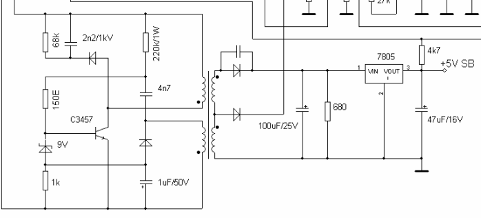
The standby voltage is needed not only to generate the enable signal (PS_ON), but also to power the PWM controller (block 3). ATX computer power supplies are most often built on the TL494 chip or its analogues. This block is responsible for controlling power transistors (block 4), voltage stabilization (using feedback), short circuit protection. In general, 494 is used very often in impulse technology, it can also be found in powerful power supplies for LED strips. Here is her pinout.

If you plan to use a computer power supply to power an LED strip, for example, it would be better if you load the 5V and 3.3V lines a little.
Conclusion
ATX power supplies are great for powering ham radio designs and as a power source for the home lab. They are quite powerful (from 250, and modern ones from 350W), while they can be found on the secondary market for a penny, old AT models are also suitable, to start them you just need to close two wires that used to go to the system unit button, the PS_On signal to they are not.
If you are going to repair or restore such equipment, do not forget about the rules for safe work with electricity, that there is mains voltage on the board and capacitors can remain charged for a long time.
Turn on unknown power supplies through a light bulb so as not to damage the wiring and PCB tracks. If you have basic knowledge of electronics, they can be converted into a powerful charger for car batteries or. To do this, the feedback circuits are changed, the standby voltage source and the block start circuits are being finalized.
The operation of any computer is impossible without a power supply. Therefore, you should take your choice seriously. After all, the performance of the computer itself will depend on the stable and reliable operation of the PSU.
What it is
The main task of the power supply is to convert alternating current and further form the required voltage for the normal operation of all PC components.
The voltage required for the operation of components:
- +12V;
- +3.3V.
In addition to these declared values, there is an additional value:
- -12V;
The power supply unit acts as a galvanic isolation between the electric current from the socket and the components that consume current. A simple example, if a current leak occurred and a person touched the case of the system unit, he would be shocked, but thanks to the power supply, this does not happen. ATX format power supplies (IP) are often used.
Overview of power supply circuits
The main part of the block diagram of the IP, ATX format, is a half-bridge converter. The work of converters of this type is to use a push-pull mode.
Stabilization of the output parameters of the IP is carried out by using pulse-width modulation (PWM controller) of control signals.
Switching power supplies often use the TL494 PWM controller chip, which has a number of positive properties:
- acceptable chip performance. This is a small starting current, speed;
- the presence of universal internal protection elements;
- Ease of use.
Simple switching power supply
The principle of operation of a conventional impulsive BP can be seen in the photo.
The first block performs the change from AC to DC. The converter is made in the form of a diode bridge that converts the voltage, and a capacitor that smooths out the oscillations.
In addition to these elements, additional components may be present: a voltage filter and thermistors. But, due to the high cost, these components may not be available.
The generator creates pulses with a certain frequency that feed the transformer winding. The transformer performs the main work in the PSU, this is galvanic isolation and current conversion to the required values.
Video: The principle of operation of the PWM controller PSU
ATX without coefficient correction
A simple switching power supply, although a working device, is inconvenient to use in practice. Many of its output parameters "float", including voltage. All these indicators change due to unstable voltage, temperature and workload of the output of the converter.
But if you manage these indicators with the help of a controller that will act as a stabilizer and additional functions, then the circuit will be quite suitable for use.
The block diagram of the PSU using a pulse-width modulation controller is simple and represents a pulse generator on a PWM controller.
Photo: IP for a computer with a PWM controller
The PWM controller regulates the amplitude of the change in the signals passing through the low-pass filter (LPF). The main advantage is the high efficiency of power amplifiers and wide possibilities in use.
ATX with power factor correction
In new power supplies for PCs, an additional unit appears - a power factor corrector (PFC). KKM removes the appearing errors of the AC bridge rectifier and increases the power factor (KM).
Therefore, manufacturers are actively producing PSUs with mandatory KM correction. This means that the IP on the computer will operate in the range of 300W or more.

Photo: 300w computer power supply circuit
These power supplies use a special inductor with an inductance higher than at the input. Such an IP is called PFC or passive KKM. It has an impressive weight due to the additional use of capacitors at the output of the rectifier.
Among the shortcomings, one can single out the low reliability of the IP and incorrect operation with the UPS during the switching of the “battery / mains” operating mode.
This is due to the small capacitance of the mains voltage filter, and at the moment of a voltage drop, the PFC current increases, and at this moment the short circuit protection is activated.
On a two-channel PWM controller
Often used in modern power supplies for a computer dual-channel PWM controllers. A single microcircuit is capable of performing the role of a KM converter and corrector, which reduces the total number of elements in the power supply circuit.
Photo: power supply circuit using a two-channel PWM controller
In the above diagram, the first part performs the formation of a stabilized voltage + 38V, and the second part is a converter that generates a stabilized voltage + 12V.
Computer power supply connection diagram
To connect the power supply to the computer, follow a series of sequential steps:

Design features
To connect the components of a personal computer to the PSU, various connectors are provided. On the back of it is a connector for a network cable and a switch button.
In addition, it can also be located on the back of the PSU and a connector for connecting a monitor.
Different models may have other connectors:

In modern PC power supplies, it is less common to install a fan on the back wall that draws hot air from the PSU. Instead of this solution, they began to use a fan on the top wall, which was larger and quieter.
On some models, it is possible to meet two fans at once. A wire with a special connector for supplying current to the motherboard comes out of the wall, which is located inside the system unit. The photo shows the possible connection connectors and the designation of the contacts.
Photo: PSU connector pin designation
Each wire color supplies a specific voltage:
- yellow - +12 V;
- red - +5 V;
- orange - +3.3 V;
- black - grounding.
Different manufacturers may have different values for these wire colors.
There are also connectors for supplying current to computer components.

Photo: special connectors for components
Parameters and characteristics
The PSU of a personal computer has many parameters that may not be indicated in the documentation. Several parameters are indicated on the side label - these are voltage and power.
Power is the main indicator
This information is written on the label in large print. The power rating of the PSU indicates the total amount of electricity available to the internal components.
It would seem that choosing a power supply unit with the required power would be sufficient to sum up the consumed indicators by components and select a power supply unit with a small margin. Therefore, a big difference between 200w and 250w will not be significant.

Photo: Switching computer power supply (ATX) at 300 W
But in fact, the situation looks more complicated, because the output voltage can be different - + 12V, -12V and others. Each voltage line consumes a certain amount of power. But the PSU has one transformer that generates all the voltages used by the PC. In rare cases, two transformers may be placed. This is an expensive option and is used as a source on servers.
In simple PSUs, 1 transformer is used. Because of this, the power on the voltage lines can change, increase with a low load on other lines, and vice versa decrease.
Working voltage
When choosing a PSU, you should pay attention to the maximum operating voltages, as well as the input voltage range, it should be from 110V to 220V.
True, most of the users do not pay attention to this and choosing a power supply unit with indicators from 220V to 240V, they risk frequent PC shutdowns.

Photo: computer power supply parameters
Such a power supply unit will turn off when the voltage drops, which are not uncommon for our electrical networks. Exceeding the declared indicators will turn off the PC, protection will work. To turn the power supply back on, you will have to disconnect it from the network and wait a minute.
It should be remembered that the processor and video card consume the highest operating voltage of 12V. Therefore, you should pay attention to these indicators. To reduce the load on the connectors, the 12V line is divided into a pair of parallel ones with the designation + 12V1 and + 12V2. These indicators must be indicated on the label.
Before choosing to buy a PSU, you should pay attention to the power consumption of the internal components of the PC.
But some video cards require a special +12V current consumption, and these indicators should be taken into account when choosing a PSU. Usually, for a PC with one video card installed, a source with a power of 500W or 600W is sufficient.

You should also read customer reviews and reviews of specialists about the selected model, and the manufacturer. The best parameters to pay attention to are: power, quiet operation, quality and compliance with the written characteristics on the label.
At the same time, you should not save money, because the operation of the entire PC will depend on the operation of the PSU. Therefore, the better and more reliable the source, the longer the computer will last. The user can be sure that he made the right choice and does not have to worry about sudden shutdowns of his PC.


