Since 1985, a G273-V generator set has been installed on KamAZ vehicles (Fig. 1.), consisting of a three-phase synchronous generator with direct-flow ventilation and a rectifier unit and an integral voltage regulator Y120M built into the generator. The generator set is designed to operate in a single-wire circuit of the car's electrical equipment with the negative terminal connected to the body. An erroneous connection to the positive terminal of the battery leads to failure of the rectifier unit and voltage regulator.
Figure 1ЇGenerator set G273-V:
1 Ї pulley; 2 Ї fan; 3 Ї cover on the drive side; 4 stator; 5 rotor; 6 Ї rotor shaft; 7 Ї rectifier unit; 8 Ї cover from the side of slip rings; 9 Ї contact ring; 10 Ї bearing cover; 11 Ї feed resistor; 12 Ї voltage regulator Y120M; 13 Ї brush holder; 14 Їseasonal adjustment switch; a Ї electrical circuit; b Ї cut; with Ї voltage regulator
The voltage regulator built into the generator brush holder is assembled according to an integrated circuit and serves to automatically maintain the generator voltage within the specified limits necessary to ensure the charging mode of the battery and the operation of consumers.
The voltage regulator has a seasonal adjustment switch (see Fig. 1). The level of the regulated voltage of the generator in the position of the switch L (summer) should be within 27 ... 28 V, in position 3 (winter) - 28.8 ... 30.2 V.
The generator is located in the upper front of the engine and is attached by two legs to the bracket, and the third to the tension bar, driven by two V-belts. The belts are tensioned by moving the generator. The gear ratio of the generator drive is 2.41.
The generator has the following pins:
"+" - for connecting the storage battery and the load;
"-" - for connection to the vehicle mass;
B - for connection to the VK output of the instrument switch and starter;
Plug on housing for phase output.

Figure 2 Ї Connection diagram of the G-273V generator system
Generator G-273V system diagram (voltage regulator PP-380 of electromagnetic type is shown): 1Ї generator rotor winding; 2 Ї generator; 3 Ї generator stator winding; 4 Ї generator rectifier; 5 Ї rechargeable battery;
- 6 Ї ignition switch; 7 Ї control lamp of the storage battery charge; 8 Ї battery charge warning lamp relay; 9 Ї fuse box; 10 Ї choke; 11 Ї temperature compensating resistor;
- 12 Ї additional resistors; 13 Ї voltage regulator. Regulator 13 maintains the generator voltage at 13.2-14.5. The serviceability of the generator is checked using a control lamp 7 in the instrument cluster and relay 8. When the ignition is turned on, when the engine (and therefore the generator) is not yet running, current from the battery flows through the relay contacts, and the lamp is on. After starting the engine and when the car is moving, the lamp should go out, since under the action of the rectified phase voltage of the generator, the relay armature should be attracted to the core and open the relay contacts.
The generation of energy for the ordered movement of particles is impossible for consumers without observing the requirements that are dictated by the connection diagram of the KamAZ generator. If, for some reason, the product is changed or removed, further operation of the car without properly performed installation manipulations will lead to numerous breakdowns.
The operation of a modern truck is inconceivable without electrical energy. Batteries that concentrate the charge need constant recharge. The generation and transmission of electricity to the circuit occurs at the expense of the generator. Variety of model connection schemes, design features, network load used, confuse the uninitiated user. The question is relevant and needs to be investigated, since it affects the condition of the car.
Generator 4001.3771-53, KamAZ Euro-2:
Purpose of the device
KamAZ vehicles are equipped with an electrical circuit built according to the classical scheme with one cable. This configuration provides one cable for consumers, the skeleton of the machine acts as cable number two. The work of the effective electric field in the scheme of the KamAZ machine is 24 volts, the indicator is achieved through the use of batteries and a device that generates an electric ordered movement of particles.
Generating device 4502.3771, Euro (3.4):

A generator is a mechanism that generates the electrical ordered movement of particles, and transfers the created product to the wiring of the machine. The purpose of the machine mechanism is to supply consumers during the operation of the power unit and in parallel to transfer the charge to the batteries for further accumulation.
The mechanism that generates the electrics of the KamAZ car works after the torque reaches 1000 revolutions and above. The initial stage of starting the motor is accompanied by the withdrawal of energy from the battery, the generating device comes into operation later.
As a rule, KamAZ automotive generating devices are equipped with a rectifier and a voltage adjustment mechanism. The rectifier converts the three-phase alternating current produced by the generator to the mains direct current. The voltage regulator smooths out the values that change due to the difference in engine speed. You can also read about.
Device types
KamAZ equipment uses installations that generate current in three phases, the generated directional movement of particles of an alternating nature, excitation - electromagnetic or self-excitation to power the on-board network. The product is put into operation due to the crankshaft, the generated current with a voltage of 27-30 V. Due to the fact that part of the directed particles is lost when passing through the rectifier and the regulator, the on-board network receives 24 V. the mechanisms that generate the current differ.
Generating devices are structurally subdivided: products equipped with a rectifier unit, adjustment is presented in the form of a separate unit; products with a built-in rectifier and voltage regulation. Modern machines are equipped with installations, simple generators are used on early modifications of KamAZ. Sometimes classic devices are also installed on new equipment, since the products are cheaper in terms of cost and are easy to maintain.
Conclusions of the KAMAZ generator:

According to the drive of the generator, they are divided: the actuation due to the V-belt, the action due to the many V-belts. The classic drive was installed on the first cars, as well as on cars with a KamAZ-740 power plant. Belts with multiple wedges are used on trucks with a Cummins power plant, as well as on engines with Euro-2 class and above.
Today the market is saturated with models of generators that differ in design. However, basic products for installation on KamAZ are: G-288, G-273-A, G-288E, G-273-V1. The first two models have been installed on trucks since their release (1970). The G-288E has been used since 1985, in the 90s and 2000s the KamAZ vehicle uses the G-273-V1 product. Imported products such as Bosch are common.
Inlet and outlet devices
The communication between the generator and the machine takes place through the network. The outer part of the device is equipped with inlet and outlet connections, the marking of which reads:
- "+" - the place of connection with the positive terminal;
- "-" - the place of connection with the negative terminal, or the body of the machine;
- "V" / "W" - the place of connection with the starting mechanism, and other devices;
- "W" / "~" - connection for turning on the tachometer (43101) and the disconnector blocking the starter;
- "+ D" / "D" - connection of the performance control lamp.
It is necessary that the connection diagram of the KamAZ 5511 generator, etc., be observed, otherwise, a breakdown is possible.
Wiring diagram for the KamAZ generator
The connection diagram of the KamAZ Euro 3 generator works according to the following principle. Contacts "AM" / "KZ" are closed when the disconnector of devices and the start device "VPS" is activated. The orderly movement of active particles from the battery goes to the 60A protection element. After, it goes to the terminals of the relay, which turns off the exciting winding (ROOV), then the contact spot "Ш", which has a connection with the "B" terminal, is suitable. Due to the ordered movement of particles, the power transistor VT2 is triggered.
Wiring diagram for the KamAZ 65115 generator:
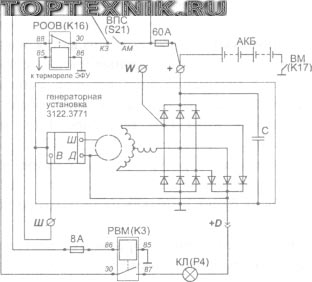
At the same time, the ordered movement of particles passes the 8A protective element and is fed to the F3 section of the "RVM" mass switch-off relay. The contact points of the relay are triggered, the orderly movement of particles through the 60A relay falls on the "KL" battery state control lamp. The lamp is triggered at the point "+ D" and then hits the exciting coil - terminal "W" voltage setting, then through the transistor VT2 to the case.
KamAZ-65115:

The exciting coil is connected to the mains of the machine, the generator is operated in classic mode. When the device generates a portion of the ordered particle movement, the voltages of the "+ D" and "+" terminals are equal. The result is the disappearance of the current in the initial excitation chain - the lamp goes out, the coil is powered by the block of auxiliary diodes. The increase in revs stimulates the entry into action of the voltage regulation mechanism.
The diagram shows a device in which a relay opening the field winding is used in motors with a flare mechanism. The bottom line is that the spark plugs consume a voltage of 19V. Starting the unit, and the beginning of the generation of electricity by the generator, provokes the combustion of candles. Thus, the relay breaks the battery disconnection circuit, immediately after the starter is triggered, so that when the unit is active, it does not disconnect from the network. The relay also turns on the primary excitation winding in order to relieve the actuation contacts of the devices and the starter.
Some machines are equipped with a generator, without the inclusion of an electric flare device in the circuit. For example, the connection diagram of the KamAZ 5320, 4310 generator.
The lamp performs a controlling function, the operation of the product indicates that the process of operation of the initial excitation circuit occurs in normal mode. When the engine starts, the lamp goes out, otherwise, the device generating energy does not cope with the function.
Wiring diagram for the KamAZ 4310, 5320 generator:

The diagram indicates:
- Q - starting disconnector;
- EL - Control lamp 2 W;
- R - Shunt resistance 50 Ohm;
- KV - Voltage regulating device (integral);
- "Ш", "+", "W", "+ D" - generator outputs.
Wiring diagram for the KamAZ 43118 generator:

Legend:
- G - Designation of the mechanism that generates the ordered motion of particles;
- GB - Source of accumulating electrical energy;
- Q1 - Disconnector for starter devices;
- Q2 - Field coil disconnector;
- C - An electrical circuit component with a capacitance of 2.2 μF;
- EL - Control lamp 24V, 2 W;
- R - Resistor, power not less than 2W, 100 Ohm;
- KV - Voltage regulating device;
- "+", "D", "W", "B", "W" - generator outputs.
KamAZ based on chassis 43118-15:

The product is used as a generator of energy for the ordered movement of particles, simultaneously with storage devices. The connection diagram of the KamAZ 43118 generator is similar to the connection diagram of machines operating on Euro 2 motors.
102 103 104 105 106 ..GENERATOR G273-V OF KAMAZ CARS
Since 1985, a G273-V generator set has been installed on KamAZ vehicles (Fig. 338), consisting of a three-phase synchronous generator with direct-flow ventilation and a rectifier unit and an integral voltage regulator Ya120M built into the generator. The generator set is designed to operate in a single-wire circuit of the car's electrical equipment with the negative terminal connected to the body. An erroneous connection to the positive terminal of the battery leads to failure of the rectifier unit and voltage regulator.
The voltage regulator built into the generator brush holder is assembled according to an integrated circuit and serves to automatically maintain the generator voltage within the specified limits necessary to ensure the charging mode of the battery and the operation of consumers.
A seasonal adjustment switch is installed on the voltage regulator (see fig. 338). The level of the regulated voltage of the generator in the position of the switch L (summer) should be within 27 ... 28 V, in position 3 (winter) - 28.8 ... 30.2 V.
The generator is located in the upper front of the engine and is attached by two legs to the bracket, and the third to the tension bar, driven by two V-belts. The belts are tensioned by moving the generator. The gear ratio of the generator drive is 2.41.
The generator has the following pins:
“+” - for connecting the storage battery and the load;
“-” - for connection to the vehicle mass;
B - for connection to the VK output of the instrument switch and starter;
Plug on housing for phase output.
Technical specifications
WARNINGS!
1. Do not connect or disconnect the plug connectors and the positive terminal of the generator set while the engine is running and the batteries are on, and do not start the engine with the positive lead disconnected from the generator.
2. Do not check the generator set serviceability by shorting the terminals “+”, B, O with jumpers to ground and to each other.
3. Do not connect the lead Ш of the brush holder, which is accessible through the window in the casing of the brush holder, with the leads “+” of the generator, B of the brush holder. This leads to failure of the regulator.
4. Do not check the serviceability of the electrical circuit and individual wires with a megohmmeter or a lamp supplied with a voltage higher than 36 V. If such a check is necessary, then first disconnect the wires from the generator set.
5. To avoid damage to the rectifier unit and voltage regulator when recharging batteries from an external source, disconnect the batteries from the vehicle's mains.
6. When washing the vehicle, protect the generator from water ingress.
Maintenance
With service 2:
Clean external surfaces from dust and dirt;
Check and, if necessary, adjust the tension of the alternator drive belts. With normal tension of the belts, the deflection boom should be within 15 ... 22 mm when pressing the middle of the larger branch with a force of 39.2 N (4 kgf). To adjust the tension of the belts, loosen the nuts securing the front and rear legs of the generator and the bolt securing the generator to the tension bar. Then deflect the generator in the direction of tensioning the belts to the required value and tighten the fasteners of the generator.
During service C (autumn), after removing the generator from the engine:
Check the condition of the brush assembly;
Blow out the rectifier unit with compressed air;
Check the reliability of the pulley fastening to the generator shaft, tighten when loose.
To check the condition of the brush-collector
Unscrew the two bolts securing the brush holder in the cover, remove the brush holder and make sure that the brushes move freely in the guides. If the brush sticks in the brush holder, wipe it and the walls of the guide hole with a cloth soaked in gasoline. Remove the brushes, inspect and measure their height. The height of the brush must be at least 8 mm from the spring to the base of the brush. Replace brushes if necessary. Disassembly of brushes is not allowed.
Slip rings are clearly visible through the hole in the cover, in which the brush holder is located. Inspect the condition of the slip rings and, if necessary, wipe with a cloth soaked in gasoline. If after that burns or dirt are found, then clean the rings with a strip of C100 glass skin, pressing it to the rings through the hole in the cover for the brush holder and turning the generator rotor.
Grind the slip rings if burn-in is not removed, the rings have an uneven surface or their wear exceeds 0.5 mm in diameter. The minimum allowable groove diameter of slip rings is 29.3 mm.
Before removing the cover from the side of the slip rings, remove the brushes together with the brush holder to avoid damage to the brushes.
Seasonal adjustment is carried out as follows:
If the outside temperature is stable at a level of 0 ° C and above, the PPR (seasonal adjustment switch) should be in the SUMMER position (L) - the left extreme position of the PPR contact screw, the screw is unscrewed;
If the outside temperature is stable at 0 ° C and below, the PPR should be in the WINTER position (3) - the right extreme position of the PPR screw, the screw is screwed in.
The regulated voltage level of the generator in the PPR SUMMER position at a load current of 20 A, a rotational speed (3500 + 200) min-1, an ambient temperature (25 + 10) ° C and a switched-off battery should be within 27 ... 28 V, and in the SPR position WINTER - 28.8 ... 30.2 V.
can be installed by any generator based on the needs of the product .. The electrical diagram of the G 273V generator is shown on Figure 53.Figure 53. Generating set Г 273В: a) - electrical circuit; b) - section; c) - voltage switching "summer" - "winter"; 1 - pulley; 2 - fan; 3 - cover from the drive side; 4 - stator; 5 - rotor; 6 - rotor shaft; 7 - rectifier unit; 8 - cover from the side of slip rings; 9 - contact ring; 10 - bearing cover; 11 - feed resistor; 12 - voltage regulator; 13 - brush holder; 14 - seasonal adjustment switch.
The generator has the following pins:
- "+" - battery and load connections;
- B- for connection to the VK terminal of the instrument switch and starter;
- "-" connection to the mass of the power plant;
- plug on the housing for the phase output.
A seasonal adjustment switch is installed on the voltage regulator built into the generator brush holder.
The level of the regulated voltage of the generator in the position of the switch L (summer) at a load current of 20 A, an engine speed (1450 + 100) min-1, an ambient temperature (25 + 10) ° C and a switched on battery should be within 27 ... 28 V, in position W (winter) - 28.8 ... 30.2 V.
On engine the generator 6582.3701, TU 37.003.1365-88 can be installed.

Figure 53-1. Generator set 3122.3771: a) - electrical circuit; b) cut; 1 - pulley; 2 - fan; 3, 8 - covers; 4 - stator; 5 - rotor; 6 - rotor shaft; 7 - rectifier unit; 9 - contact ring; 10 - bearing cover; 11 - feed resistor; 12 - voltage regulator; 13 - brush holder; C - 2.2μF capacitor.
Attention!
- Do not connect or disconnect the plug connectors and the positive terminal of the generator set with the engine running and the batteries on, and do not start the engine with the positive lead of the generator disconnected.
- It is not necessary to check the serviceability of the generator set by shorting the terminals "+", "B" and "-" with jumpers to ground and to each other.
- Do not connect the "Ш" terminal of the brush holder, which is accessible through the window in the brush holder casing, with the terminals "+" and "B" of the generator. This leads to failure of the regulator.
- It is impossible to check the health of the electrical circuit and individual wires with a megohmmeter or a lamp, to which a voltage higher than 26 V is applied, with the generator not disconnected.
- Do not check the rectifier unit from a direct current source with a voltage of more than 24 V, from an alternating current source, as well as without an indicator connected in series with the rectifier unit.
- To avoid damage to the voltage regulator when recharging batteries from an external source, you must disconnect the batteries from the network.
- When washing engine it is recommended to protect the generator from water ingress.
Electrical diagram and operation of the G272 generator of the KamAZ car
The first models of KamAZ vehicles were equipped with the G272 generator. This 28 V generator had twice as many turns of a thinner wire in the stator windings than the G250. The excitation winding was also wound with a thinner wire and was calculated for a voltage of 28 V.
There were no additional charge control elements in the electrical circuit (Fig. 6), and the operation of the generator was monitored using an ammeter.
In the brush assembly of the generator, both brushes were made insulated from the mass and had the inscriptions Ш1 and Ш2.
To regulate the voltage, a regulator model PP356, made on the basis of silicon transistors, was used. One output of the excitation winding was connected to the on-board network, and the second to the voltage regulator.
Rice. 6. Wiring diagram for connecting the G272 generator on a KamAZ car: ST - stator winding; ОВ - excitation winding; RN - voltage regulator PP356; D1 ... D6 - diodes; ВЗ - switch in the ignition lock
Electrical diagram and operation of the G273 generator of the KamAZ car
Currently, more advanced G273 generators are used for KamAZ vehicles.
To unify the G273 generator with the most common G250 generator, this generator is made on the basis of its parts.
To obtain a voltage of 28 V instead of 14 V, the stator windings are rewound. On the back cover of the generator there is a make-up resistor and an integral voltage regulator Ya120M.
To match the speed of the engine and generator rotor, the pulley was replaced. The rest of the details remained unchanged.
Due to the unification, the number of spare parts has been reduced and the production technology has been simplified.
The electrical diagram of the generator is shown in Fig. 7.
Since the excitation winding remained unchanged and is designed for a 14 V supply, it is connected to the zero point of the phases. When the generator is operating at this point, the voltage is 14 V.
For self-excitation of the generator, a current of 0.3 A is supplied to the excitation winding through an additional wirewound ceramic feed resistor. This current provides the creation of an initial magnetic field in the pole halves of the rotor. When the engine is started, the generator comes into operation and the voltage at the zero point gradually reaches 14 V.

Rice. 7. Wiring diagram for connecting the G273 generator on a KamAZ car: ST - stator winding; ОВ - excitation winding; RN - voltage regulator Y120M; D1 ... D6 - diodes; ВЗ - switch in the ignition lock; RП - feed resistor
If you remove the feed resistor, then when the engine is started, the generator will not be able to be excited and its rotor will rotate without load.
The contacts in the ignition lock switch a small control current of the integral controller.


 Cobra")


