The device below has good quality Sounds and low noise levels, and also has the function of bypassing (direct response), at the same time, the simplicity of the scheme will not scare off beggar radio amateurs. The basis of the passive part of the scheme includes the development described by E.J.James "Ohm in 1948, and all the device together brings to the work of Baxandall" A sample of 1952 :) Looks amplifying cascade, in this case Oh, who can raise the amplitude, "eaten" (the amplitude regulator falls five times or -13db!) Dreadful. Analyzing the sources widely known to any radio amateler (in which some historical inaccuracies are observed), it was decided to experiment with this little thing:
Unfortunately, the real charts of the frequency response did not have time to remove, but we give the modeling result in the Tone Stack Calculator program. This scheme is notable for the use of R5-R6, which provide a narrower raising of the frequency without affecting the middle. These resistors are not in the development of E.J.James "a, so the simulation will occur without them :) However, it will not affect the overall impression of the graph, just the high frequency lift band will be wider.

But I would like more: an even greater rise in the LF and in particular HF, so to speak with a margin, although in your case everything can be completely different. Rather, not in your case, but in the case of your acoustics :). For example, from the experience of the production of the Berdy Radio Sadness of Vega 50As-106, the low frequency frequency adjustment in RRR UP-001 did not fit at all, since only the region of the upper bass (200-250 Hz, the bass is difficult to call, rather than the hum). However, on the acoustic systems produced by the Ragge Radiotehnika RRR S50B, it was possible to achieve acceptable sound quality. Although all this is pamping, as it corrects only the impression from listening, adjusting the frequency response and, if the amplifier is damaged, is carried out by other circuitry, for example, with parametric equalizers with adjustments not only in strengthening, but also with the possibility of moving the raised frequency and goodness. But we have not gathered here to correct the flaws of the dear acoustics?

Total +6 dB at the main low frequency, and +5 dB on high. The dB dB in the middle frequency area is decided to raise up to the OU. I confess, it became a little bit too much. In the circuit, the rotation of the regulators is difficult to achieve a solid response (rather not to achieve at all), so it is decided to add a device that turns off the ramp. This may be useful when operating with your amplifier more "advanced" equalizer. Simple closure of the entrance and exit of the passive part or all the temperature (in the first case, the C3 capacitor closes and as a result, the top will fall, in the second - the adjustment of the RF and the LC is preserved, the truth in small limits) can not do here. Therefore, it is possible to carry out elementary switching on the relay with cake contacts (type RES-9, RGK-14, etc.).
It is worth separately touched upon the displaced theme of capacitors in the chain block. In its subjective experience of exploitation of the well-known preamp of Shmelev, in the design of which was used to unintellite the ceramics of imported production, widespread in stores, the output signal was saturated with harmonics, which was felt on the rumor. Perhaps in the blind test of this collector with other capacitors, I would not have noticed this, but nevertheless I have deeply deposited in memory. In this design, I decided to use exclusively capacitors on a paper basis. Of course, here I will not describe the experience of using imported capacitors for hundreds of dollars, but as they say, than rich :). Capacitors of the BMT-2, BM-2 and MBM series of the accumulated reserves were pulled out.
So, when using the data of the capacitors, the first thing to be done is to measure their container and examine on external damage (especially for BMT-2). Among the ten samples of the Condenters of the MBM series, 90% had an excess of the nominal capacity by 40-50%, which is two more tolerances. The measurement of the container allows you to select capacitors into pairs for 2 channels to provide symmetrical adjustment. The first inclusion and verdict is uniquely preferable to the use of Chinese ceramics. To his shame, I could not find a paper capacitor in the RF circuit, so the capacitor of the CTC series was used, was widely used in lamp TVs and other equipment. Among other things, this capacitor has good thermal stability. Silver plated on sound did not affect the sound :) (although after replenishing the luggage of knowledge about this condenser, the sound gradually began to become painful and ... :)). Graphics that happened to remove:
Regulators are rotated to the maximum:

Regulators are rotated at a minimum:

The scheme of the resulting device:

Characteristics of this rainbreaker:
- The coefficient of harmonic,%: not more than 0.02.
- Adjustment range, not less: LC + -16 dB, RF + -17 dB.
- Input: ~ 1v.
CG indicators, signal / noise depend on the applied OU. The choice fell on TL072, (this is a dual OU of the company ST) by virtue of its cheapness and prevalence. Operations such as NE5532, NJM4558, LM358 are perfect here. It is possible to experiment with single OU (with a fallen alteration of PP) TL071, NE5534, kr5444ud1,2, k157ud2 (with correction chains) and so on. With paper capacitors and OU in a gold case than not rarity? For operational replacement of the chip (if you prefer another OU), it is recommended to pre-install the DIP-8 panel to the appropriate location.
To power the active part of the device, a parametric voltage stabilizer is used to two shoulders + and - without using any amplifying elements, since in this scheme the total consumption current is less than the rated current of the stabilion. To smooth out the residues of pulsations caused by pulsations of the power supply unit UMP, there are two electrolytes in the diagram. Their container is small to provide low inertia. Such a small set gives a low background when operating the device.

Of course, to ensure the minimum background of this is not enough. Reduce the background can help grounding of variable resistors. Some groups of regulators have a separate output (for example, SP3-33-23). In my disposal turned out to be widespread resistors of the B-Group (they are not suitable for adjusting the balance), the case of which, after processing the sandpaper, I have grounded. The lands reduced to one selected point (the body of the low frequency controller), from where they sent them to the power of the power supply unit Umzch. Photo device and printed circuit board:

The size pCB 140х60 mm, here you can download a file in format .lay.. I wish you success in repetition! .
Discuss the temboalk article
Part 1. On how to make the IS "sound".
I have worked the amplifier for a long time on not all your favorite, but very popular chipTDA 7294 in Datashantovsky »Includes with the debate onLM. 1036. This tandem replaced the tumors stood in the "Romance-222C" amplifier on the KT808 and the timbre / volume regulators K174UN10 / K174UN12, the sound of which, well ..., you know what. At that time, the new version of the sound was completely satisfied with the sound, but ... I somehow came across the eyes of the audiookiller about the amplifier onTDA 7294 with adjustable output resistance according to the ITUN scheme. Without how long thinking, I saked this inclusion from my ending. I made sure that really, high "awesome", and low, well, just "no longer needed" :). The sound in such a scheme was already clearly more interesting than in Datascious. I do not remember how ways, but I finally got to the site of Nikolai Lishmanova, whoLincor . And there - an article about the amplifier onTDA 7294 with "Fucking feedback» - MF. 1 is called ... Since then (already a year and a half) in Romantics, the Upper is working for this scheme. There is a certain "highlight" in his sound ... Rather, even, Izya Package :). Read proMF. 1 here: http://lincor-lib.narod.ru/amps2.htm. And here is the scheme itself in my "implementation":

Fig.1-diagram power amplifier.
Power amplifier is carried out by standard scheme:

Fig. Fig. The power supply unit for power amplifier.
Part 2. The fact that the "porridge will not spoil" a good temboocle ".
In good descendant should stand a good operator. It is he will determine the "character" of the sound.As follows from project reviewsProstor and Tale 3 U , the qualitative debt "causes" to sound like this, it would seem to be familiar to the films on chips. I decided and I go to the experiment and "twist"MF. 1 collector OT.TALE 3 U. , look at which you can here: http://yooree.narod.ru/tale3u.html. The scheme of this miracle looks like this:

Fig.3 diagram of the collector.
OU can be used asLT 1356 and LT 1362. The latter, as on my hearing, it sounds even a little more interesting, but I can be mistaken. Here, most importantly, take into account the rather noticeable heating of the chipLt. 1362, which may be a consequence of self-excitation. Therefore, it is advisable to verify the absence of generation. All items located in the diagram below the pointsa., b., c. Sold directly on the outputs of variables of the grain resistors.
You can feed it as a "budget" option on two stabilizers of the 7812-7912 series and from the "original" forTALE 3 U. BP, powered it from a power amplifier BP. The scheme of the "budget" version of the stabilizer may look like this:

Fig.3 Scheme of the power supply to the ramp.
Epilogue
In this project, I tried to combine two schemes that have already deserved recognition of self-dealers, thanks to its recognizable and "pretty" sound. This amplifier has a very "mobile" and "alive" if this can be said about sound. Bass - "monumental-reinforced concrete" and worked, sch and rag are easy and detailed. Vocals are very expressive and transparent. The columns "play" as if "into space", and not "into ourselves." A familiar seemingly music, as if received a new sound. So my regularly thanks to Yuri, audiookiller and linkor for the invisible, but very effective participation in creating this amplifier :)
Circuits of simple homemade timbre regulators (rapid), which are made on the CT3102 transistor, KT315 and on the K140ud8 operating amplifier (K140UC20, K140UC12).
Schemes of rates contain minimum parts and can be collected by novice radio amateurs. These rates can be applied in a complex with self-made audio-producing audio equipment: in the amplifiers of the LF, microphone amplifiers, mixers, and the like.
Two-band timbre regulator on the transistor
One of the numerous examples of the schemes of the Tonmbra TombbbbMS and HF for UCH on the transistors is presented. Limited electronic scheme Preceded by a cascade with low output resistance, for example, an emitter repeater (cascade with a common collector) or OU.
This provides low output resistance of the preceding stage and the normal operation of this regulator.
Fig. 1. Scheme of two-band regulator of the timbre (NC, RF) on the transistor.
Elements for the scheme:
- R1 \u003d 4.7K, R2 \u003d 100K (LF), R3 \u003d 4.7K, R4 \u003d 39K, R5 \u003d 5.6K,
- R6 \u003d 100K (HF), R7 \u003d 180K, R8 \u003d 33K, R9 \u003d 3.9K, R10 \u003d 1 K;
- C1 \u003d 39H, C2 \u003d 30MKF-1 OBRF, SZ \u003d 5MKF-20MKF,
- C4 \u003d 2.2N, C5 \u003d 2.2N, C6 \u003d 30MKF-100MKF;
- T1 - KT3102, KT315 or similar.
Two-band tone regulator on OU
Figure 2 shows an example Schemes of two-band regulator Tonmbra LF and RF For UCH on the operating amplifier (OU). This electronic scheme precedes the Cascade on the OU. This provides low output resistance of the preceding stage and the normal operation of this regulator.
To increase the stability of the operation of the scheme (on HF), it is advisable to stunify the power conclusions of the OU capacitors 0.1 μF, for example, the KM6 type. Capacitors are connected as close as possible to the OU.
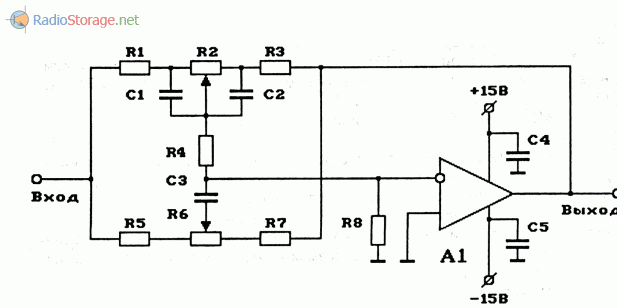
Fig. 2. The diagram of the two-band regulator of the timbre (LF, HF) to the OU.
Elements for the scheme in Figure 2:
- R1 \u003d 11K, R2 \u003d 100K (LF), R3 \u003d 11K, R4 \u003d 11K, R5 \u003d 3.6K, R6 \u003d 500K (HF), R7 \u003d 3.6K, R8 \u003d 750;
- C1 \u003d 0.05MKF, C2 \u003d 0.05MKF, SZ \u003d 0.005MKF, C4 \u003d 0.1 ICF-0.47MKF, C5 \u003d 0.1 μF-0.47MKF;
- OU - 140UD12, 140UD20, 140D8 or any other OU in type inclusion and preferably with internal correction;
Three-band tomb control on OU
The three-band timbre control gives the best feedback result than a two-band regulator.
Figure 3 shows an example of the scheme of the three-wire chain of the Tonmbra of the NCH, SC and HF for UNG onto the OU. This electronic scheme precedes the Cascade on the OU. This provides low output resistance of the preceding stage and the normal operation of this regulator.
To increase the stability of the scheme (on HF), it is advisable to draw the power conclusions of the OU capacitors 0.1 μF. Capacitors are connected as close as possible to the OU.
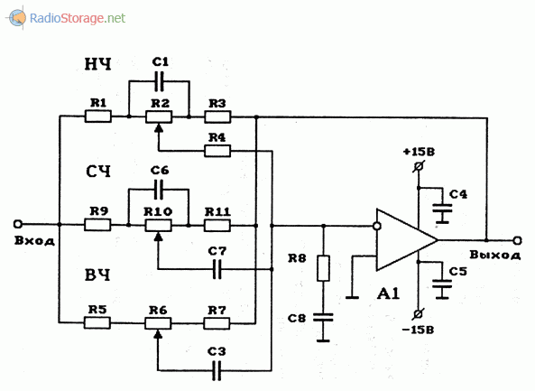
Fig. 3. Scheme of a three-track tone regulator (NCH, SC, HF) on the OU.
Elements for the scheme in Figure 3:
- R1 \u003d 11K, R2 \u003d 100K (LF), R3 \u003d 11K, R4 \u003d 11K, R5 \u003d 1.8K, R6 \u003d 500K (HF),
- R7 \u003d 1.8K, R8 \u003d 280, R9 \u003d 3.6K, R10 \u003d 100K (sch), R11 \u003d 3.6K;
- C1 \u003d 0.05MKF, C2 - missing, sz \u003d 0.005MKF,
- C4 \u003d 0.1 ICF-0.47MKF, C5 \u003d 0.1 μF-0.47MKF,
- C6 \u003d 0.005MKF, C7 \u003d 0.0022MKF, C8 \u003d 0.001MKF;
- OU - 140UD8,140UD20 or any other OU with internal correction (preferably) and in type-inclusion.
Literature: Rudomedov E.A., Rudomets V.E. Electronics and Spy Passion-3.
A certain person has recently addressed to assemble the amplifier of sufficient power and separate gain channels at low, medium and high frequencies. Before that, more than once already collected for himself as an experiment and, I must say, the experiments were very successful. The quality of sound even inexpensive columns are not very high significantly improved compared, for example, with an option for using passive filters in the speakes themselves. In addition, it is possible to quite easily change the frequencies of the bands and the gain of each individual strip and, thus, it is easier to achieve a uniform response of the entire soundsweight path. In the amplifier, ready-made schemes were applied, which before that were repeatedly tested in simpler structures.
Structural scheme
The figure below shows the channel 1 scheme:

As can be seen from the scheme, the amplifier has three inputs, one of which provides for a simple possibility of adding a preamplifier to the vinyl player (with such a need), the input switch, the pre-amplifier-ramp (also three-band, with adjustable levels of HF / sch / NC), Volume control, Filter block for three bands with adjustment of the level of enhancement of each band with the possibility of turning off the filtering and power supply for the terminal power amplifiers (unstabilized) and the stabilizer for the "low-current" part (reinforcing pre-cascades).
Preliminary amplifier
As it was applied a scheme, more than once, proven to it, which, with its simplicity and accessibility of parts, shows pretty good characteristics. The scheme (like all subsequent) was published in the Radio magazine and then repeatedly published on various websites on the Internet:
The input cascade on DA1 contains the gain level switch (-10; 0; +10 dB), which simplifies the coordination of the entire amplifier with different sources by the signal sources, and the timbre regulator is directly assembled on DA2. The diagram is not capricious to some scattering of the items and does not require any establishment. As an OU, any chips used in amplifier sound paths can be used, for example here (and in subsequent schemes) I tried imported V4558, TL072 and LM2904. Any suitable, but better, of course, choose OU variants with a smaller level of own noise and high speed (increasing coefficient of input voltage). These parameters can be viewed in reference books (datasheets). Of course, it is not necessary to apply this scheme that is not at all, it is quite possible, for example, not a three-way, but the usual (standard) two-band debt. But not the "passive" scheme, but with the cascades of strengthening-coordination at the entrance and exit on transistors or OU.
Block filters
Filter circuits, also, if desired, you can find a lot, as publications on the topic of multibone amplifiers are now enough. To facilitate this task and simply for example, I will give here several possible schemes found in various sources:
- A diagram that was applied by me in this amplifier, since the frequencies of the partitions were just the following, which were needed to "customer" - 500 Hz and 5 kHz and did not have to recalculate anything.

- The second scheme, easier to OU.
And another possible scheme, on transistors:
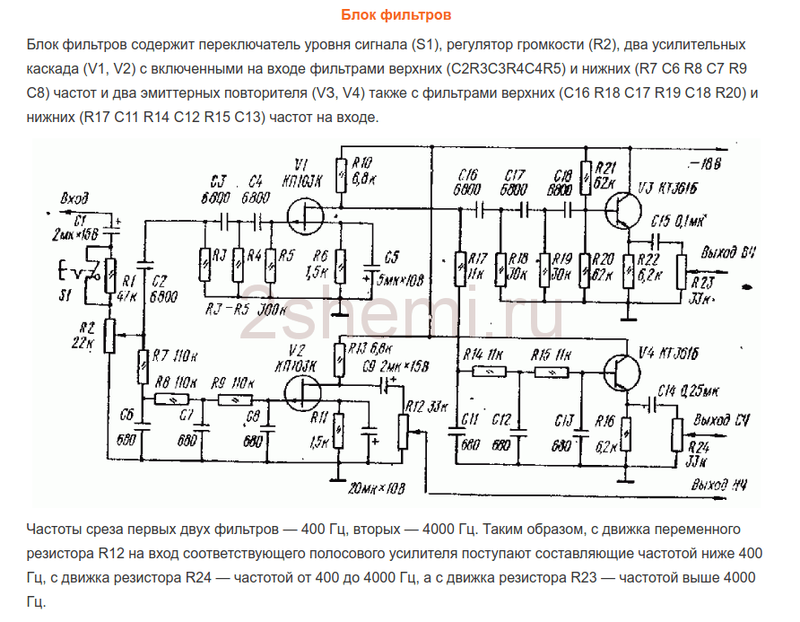
As you already wrote, I chose the first scheme due to quite high-quality filtering of the bands and compliance frequencies of the bands as specified. Only on the outputs of each channel (bands) were added simple regulators amplification level (as it is done, for example, in the third scheme, on transistors). Regulators can be delivered from 30 to 100 com. Operating amplifiers and transistors in all schemes can be replaced with modern imported (taking into account the basement!) To obtain the best parameters of the schemes. No configuration require all these schemes if you do not need to change the frequencies of the bands. Unfortunately, I have no possibility to recalculate these frequencies of the section, since the schemes were sought for example "Ready" and detailed descriptions It was not attached to them.
The filter block diagram (first scheme of three) was added the ability to disconnect filtering through Mys and HF channels. To do this, two P2K button switching switches were installed, with which you simply close the connection points of the filters inputs - R10C9 with their respective outputs - "Output of the HF" and "SC-output". In this case, on these channels there is a complete beep.
Power amplifiers
From the output of each channel filter, the TSG signals are fed to the power amplifier inputs, which can also be collected according to any of the known schemes, depending on the required power of the entire amplifier. I did the umzch at a well-known scheme from the Radio magazine, No. 3, 1991, p.51. Here I give a link to the "original source", since about this scheme there are many opinions and disputes on the reason for its "quality". The fact is that at first glance it is a scheme of the amplifier class "B" with the inevitable presence of distortion of the type of "step", but it is not. The diagram used current control of the output cascade transistors, which allows you to get rid of these shortcomings in the usual, standard inclusion. At the same time, the scheme is very simple, not critical to the details applied and even transistors does not require a special preliminary selection by parameters, besides, the scheme is convenient because the powerful output transistors can be placed on one heat sink in pairs without insulating pads, since the collectors' conclusions are connected at the point " exit ", which greatly simplifies the installation of the amplifier:

When setting only it is important to select the correct modes of operation of the transistors of the forefront (selection of resistors R7R8) - on the bases of these transistors in the "resting" mode and without load at the output (speaker) there should be a voltage in the range of 0.4-0.6 volts. Power supply for such amplifiers (them, respectively, should be 6 pieces) raised to 32 volts with replacing the output transistors for 2SA1943 and 2SC5200, resistance to resistors R10R12 should also be increased to 1.5 com (for "relief of life" Stabilians in the chain Eating input OU). The OU was also replaced by VA4558, while the "zero setting" chain is not needed (Outputs 2 and 6 in the diagram) and, accordingly, the basement is changed when the microcircuit soldering. As a result, when checking each amplifier, it issued a power to 150 watts to this scheme (briefly) with a completely adequate degree of radiator heating.
UHC power supply
As a power supply, two transformers with blocks of rectifiers and filters along the usual, standard diagram were used. To power the LB band channels (left and right channels) - a 250 watt transformer, a rectifier on diode assemblies of the MBR2560 type or similar and condensers of 40,000 μF x 50 volts in each power shoulder. For sch and RF channels - a transformer with a power of 350 watts (taken from the burnt receiver "Yamaha"), the rectifier - the diode assembly of TS6P06G and the filter - two capacitors of 25,000 microf x 63 volts on each shoulder power. All filter electrolytic capacitors are drawn by film capacitors with a capacity of 1 μF x 63 volts.
In general, the power supply may be with one transformer, of course, but when it is appropriate. The power of the amplifier as a whole in this case is determined exclusively by the power source capabilities. All preliminary amplifiers (grooboders, filters) are also powered from one of these transformers (can be from any of them), but through an additional block of a bipolar stabilizer, assembled on MS type of roll (or imported) or any of the type schemes on the transistors.
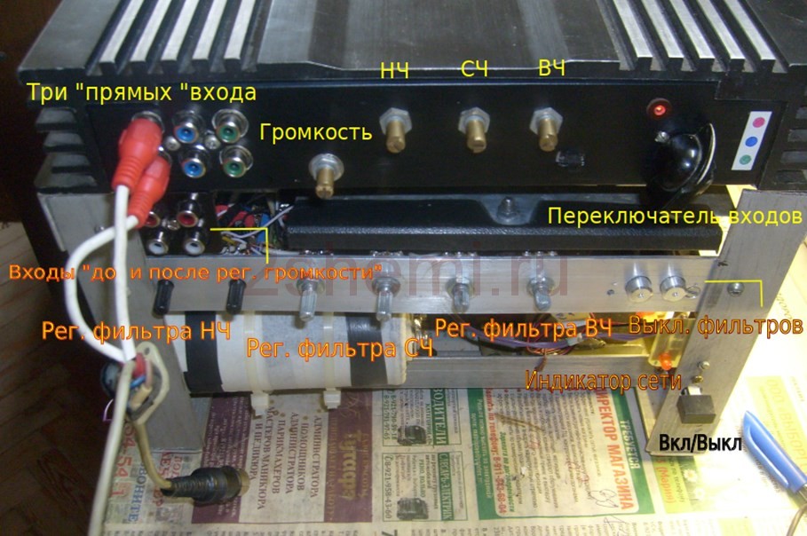
Design home-made amplifier
This, perhaps, was the most difficult moment in the manufacture, since the suitable finished body was not found and had to invent the possible options :-)) In order not to sculpt a bunch of separate radiators, I decided to use the radiator body from the automotive 4-channel amplifier, quite large sizes, about this:

All "insides" were naturally extracted and the layout turned out to be approximately such (unfortunately I did not do the corresponding photo):

- As can be seen, there are six Radiator Caps of the UMPs and the preamplifter preamplifier fee. The filter block fee no longer climbed, therefore, the design of the aluminum corner was then fixed (it can be seen in the figures). Also, in this "frame" transformers, rectifiers and filters of power supplies were installed.
The view (front) with all switches and regulators was like this:
Rear view, with pads of outputs on speakers and fuse block (since no electronic protection schemes were made due to a lack of space in the design and not to complicate the scheme):

In the subsequent frame from the corner, it is assumed, of course, to close with decorative panels to give a product of a more "product" species, but it will be already the "customer" itself, according to his personal taste. And in general, in terms of quality and sound power, the design turned out to be quite decent. Material author: Andrei Baryshev (especially for the site website).
I decided to listen to how the class D is the IRS2092 amplifier. After short
Search for Ali was made an order. For the sake of interest, "how it sounds" for him was also ordered and temboels.
Since the amplifier is still on the road and the debt - already came
Make a review while on it. How will the amplifier comes to review and on
His measurements.
The board came in an envelope with the pupil. The kit includes the sam and
Four handles on resistors. Flux Vise washed the soldering less
Neat. Wiring board average. Regulators in the photo - from Lev to the right - HF, Sch, LF, Volume.

On the board installed OU NE5532P 
Also on the board are the power stabilization chains (L7812 and L7912) and rectifier.
Can be served aC voltage with a power transformer
fees.
The scheme of the regulator is similar to this 
Different quantities of some resistors and the absence of some passing
capacitors.
Now the most important thing is tests.
Tested on this map 
Creative Sound Blaster X-Fi Titanium Pro with a small refinement is completely shielded by the reverse side of the printed circuit board, the output OPA is replaced by OPA2134, all capersion capacitors are shunted by ceramics.
Ahh (pink color - from entering the output of the miner, in blue
- Through the collectors - all tone regulators in the middle position) 
See a small rise on on low frequencies (below 200Hz) and the rank on
High (above 6kHz)
NC regulators in extreme positions 
SC regulators in extreme positions 
RF regulators in extreme positions 
Of the book "THD", the right channel is followed by a challenge for comparison (from the output of the card to
Login), bookstem debades 0.016%, I would like smaller of course. I tried to put OPA2134 instead of native OU, the distortions decreased slightly but insignificantly, most likely because of the fee not quite correctly. 
The dependence of the books from frequency (the right channel is followed by the rainbill,
Pink color on the chart) 
The collector does not invert the signal phase (the right channel is followed by the rainbill,
Pink color on the chart) 
Pretty medium in quality unit, for home crafts will go if satisfied with the book.
Put in the planned strengthening is unlikely to be due to high
harmonic distortion. I will breed a fee myself, and collect the collector.
I hope the infa was helpful.


 in Photoshop How to make a grid in photoshop CS6")


