For those who are just starting to take their first steps in electronics, it is important to start somewhere. Well, we suggest that you familiarize yourself with ideas that may come in handy in the future and at the same time give an idea of how something should be done. What to choose if you want to make simple ones with your own hands? Here are options that can be used in everyday life.
Simple power regulator for smooth switching on of lamps
This type of device is widely used. The simplest is a conventional diode, which is connected in series with the load. Such regulation can be used to prolong the life of the incandescent lamp, as well as to prevent overheating of the soldering iron. They can also be used to vary the power over a wide range of values. The easiest ones will come first electronic homemade products do it yourself. You can see the diagrams here.
How to protect against line voltage fluctuations

This device disconnects the load if the mains voltage is out of range. As a rule, within the normal range, a deviation of up to 10% of the standard is considered. But due to the peculiarities of the energy supply system in our country, such a framework is not always respected. So, the voltage can be 1.5 times higher, or much lower than necessary. The result is often unpleasant - the equipment fails. Therefore, there is a need for a device that will disconnect the load before something has time to burn out. But when creating such a homemade product, you need to be careful, since the work will be carried out with considerable stress.
How to make a safety transformer
In various electronic designs, transformerless power supplies are often used. Usually, such devices have low power, and to avoid electric shock, they are placed in an insulating plastic case. But sometimes they need to be configured, and then the protection is opened. To avoid possible injury, a safety isolation transformer is used. It will also be useful when repairing such devices. Structurally, they consist of two identical windings, each of which is designed for the network. As a rule, the power of transformers of this type fluctuates in the range of 60-100 W, these are the optimal parameters for tuning various electronics.
A simple source of emergency lighting

What to do if it is necessary so that in the event of a power outage, the illumination of a certain area remains? The answer to such calls can be an emergency luminaire based on the standard energy saving lamp, the power of which does not exceed 11 watts. So if you need the light somewhere in the corridor, utility room or workplace, this homemade product will have to be in place. Usually, when voltage is present, they work directly from the mains. When it disappears, the lamp begins to operate on battery energy. When the mains voltage is restored, the lamp will work and the battery will be automatically charged. The best do-it-yourself electronic homemade products were left at the end of the article.
Soldering Iron Boost Power Regulator

In cases where it is necessary to solder massive parts or the mains voltage often drops, the use of a soldering iron becomes problematic. And a step-up power regulator can help out from this situation. In these cases, the load (i.e. the soldering iron) is supplied with a rectified mains voltage. The change is carried out using an electrolytic capacitor, the capacity of which makes it possible to obtain a voltage greater than 1.41 network. So, with a standard voltage value of 220 V, it will give 310 V. And if a drop occurs, say, to 160 V, then it turns out that 160 * 1.41 = 225.6 V, which will allow you to operate optimally. But this is just an example. You have the opportunity to make a scheme that suits your specific conditions.
The simplest twilight switch (photo relay)

As new parts are created, fewer and fewer components are now needed to make a piece of equipment. So, for an ordinary twilight switch, only 3 of them are needed. Moreover, due to the versatility of the design, multipurpose use is also possible: apartment building; to illuminate the porch or courtyard of a private home, or even a separate room. Pointing to the features of such a design as a twilight switch, it is also called a "photo relay". You can find many implementation schemes that were made either by hobbyists or industrialists. They have their own set of positive and negative properties. Negative properties are usually called either the need for a constant voltage source, or the complexity of the circuit itself. Also, when buying cheap and simple parts or whole sets, they often complain that they simply burn. The functionality of the circuit is based on three components:
- Photocell. Usually, it is understood as photoresistors, phototransistors and photodiodes.
- Comparator.
- Triac, or relay.
When there is daylight, the resistance of the photocell is low and does not exceed the response threshold. But as soon as it gets dark, the structure will be turned on at the same moment.
Conclusion
Here are some interesting do-it-yourself electronic homemade products. The main thing in cases when something does not work out is to keep trying, and then everything will succeed. And having gained experience, it will be possible to move on to more complex schemes.
Simple logic probe
A simple logic probe consists of two independent threshold devices, one of which is triggered when the input voltage corresponds to a logic "1", and the other to a logic "O".
When the voltage at the probe input is between 0 and +0.4 V, transistors V7 and V8 are off, V9 is off and V10 is on, the green LED V6 is on, indicating "0".
With an input voltage of +0.4 to +2.3 V, transistors V7 and V8 are still off, V9 is on, V10 is off. LEDs are off. When the voltage is higher than +2.3 V, transistors V8, V9 open and the red LED V5 lights up, indicating "1". Diodes V1-V4 serve to increase the voltage at which the threshold device is triggered, indicating "1".
The current transfer coefficient of the transistors must be at least 400. The adjustment is made by selecting R5 * and R7 * according to the clear operation of the threshold devices at a voltage from +0.4 V to +2.4 V.
Network "CONTROL"
Typically, neon finder probes are used to detect line voltage. Alas, in our time, even such a probe is not easy to obtain. But it is quite simple to assemble a control device, the diagram of which is shown in the figure.
The circuit consists of a transformerless rectifier, a stabilizer and a sound signaling device on transistors VT1 and VT2. When the probe probes are connected to the network, the circuit receives a stabilized power supply with a voltage of 5 V, and the sound generator is triggered. Installation is carried out in a hinged way. Resistors - MLT type. Capacitors C1 and C2 - K73-17, SZ and C4 - any electrolytic, transistors VT1 and VT2 can be replaced with any low-power ones with the appropriate conductivity structure. A dynamic head with a voice coil impedance of 6 - 10 ohms.
The device must be assembled in a durable plastic case. Particular attention should be paid to the insulating properties of the housing, as required by work with transformerless structures. The desired tone of the signal can be selected by the capacitance of the capacitor C4.

Simple transistor tester
A simple transistor tester allows you to check the performance of n-p-n and p-n-p bipolar transistors.

The tested transistor together with one of the installed in the device (depending on the structure of the tested transistor, determined by the position of the switch S1) V1 or V2 forms a multivibrator that generates low frequency oscillations. The indicators of the presence of oscillations, and therefore the health of the tested transistor, are the LEDs V3 and V4, which flash with a frequency generated by the multivibrator.
This device can be used to test low, medium and, in some cases, high power transistors. Using the resistor R1, the (approximately) amplifying properties of the tested low-power transistor are estimated - the greater the resistance of the inserted part of the resistor, at which the multivibrator is still operating, the higher the current transfer coefficient of this transistor. The device is powered by one 3336L battery.
Automatic light switch
Automatic - light switch allows you to automatically turn off the lighting during daylight hours.

The machine consists of a light sensor - a photoresistor and a photo relay, made on transistors VI, V2, an executive circuit on thyristors V4, V10 and a full-wave rectifier on diodes V6, V7. The machine works as follows. With a decrease in illumination, the resistance of the photoresistor R3 increases from 1 ... 2 kΩ to 3 ... 5 MΩ, which leads to an increase in the collector current of transistors VI and V2. As a result, the thyristor V4 opens, the chain R7, C3, V9 generates a pulse that opens the thyristor V10, and the lighting lamps turn on. With an increase in the illumination of the photoresistor, its resistance decreases, and the collector current of the transistor V2 also decreases, which leads to the blocking of the thyristors V4 and V10. The lighting lamps go out, and the capacitor C3 is discharged through the diode V8 and resistors R5, R6 and R7. The switch-on threshold of the machine is set by the resistor R1.
Details .
Variable resistor R1 of the SPO-0.5 type, resistors of the MLT-0.5 type; photoresistors of types SF2-2, SF2-5 or FSK-1; transistors - any low-frequency structure p-p-p with B> 50; capacitor C2 of type MBM, MBHTs, MBGP for a voltage of 400 V.
When setting up, it is required to select resistors R5-R7, achieving reliable opening of the thyristor V10 at a given (resistor R1) threshold of the photo relay.
|
Transformerless power supply To power devices with a current consumption of up to 30 mA, simple network power supplies can be used, in which, instead of step-down transformers, two capacitors are used for an operating voltage of at least 300 V.
Resistor R1 is used to discharge the capacitors after turning off the unit from the network. The parameters of such blocks with various containers C1 and C2 and diodes VD3 and VD4 are shown in the table.
|

Power supply for analog and digital microcircuits
The power supply for analog and digital microcircuits consists of three stabilized rectifiers, two of which form a bipolar 12.6 V voltage supply with separate regulation.

Adjustment is made by trimming resistors R6 and R9. The lower (according to the diagram) stabilizer provides a voltage of 5 V, which can also be regulated by the resistor R10.
The unified power transformer TAN 59-127 / 220-50 can be replaced with a self-made one with a magnetic circuit Ш 12 X 20. Mains winding I for 220 V must have 3000 turns of wire PEV-2 - 0.12, winding II - 180 turns PEV-2 - ODZ , winding III - 220 turns of PEV-2 - 0.38 and winding IV - 70 turns of wire PEV-2 0.41. The different number of turns in windings II and III with the same voltage at the output of the stabilizer arms in this design of the power supply is explained by the fact that 60 mA is consumed from the upper (according to the diagram) arm, and 350 mA from the lower one. If, according to the operating conditions, these currents should be equal, an equal number of turns of wire of the same diameter should be wound.
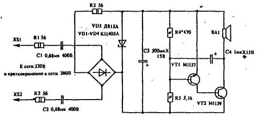
Instead of "neon"

Capacitor C1 is used as a wattless resistance; diodes VD1-VD4 protect the VA1 speaker from sudden surges of current at the moments of on-off; resistor R1 serves to discharge C1 after turning on the device.
Capacitor C1 must have a voltage of at least 400 V and a capacity of 1-2 μF. Speaker - 0.25GD19 or any other, with a power of more than 0.25 W with an internal resistance of 6-10 ohms. Instead of a speaker, you can use a telephone capsule, for example, "TON-1", while the capacitance C1 is reduced to 0.01 μF. The device is assembled by surface mounting in a dielectric material housing.
High precision thermostat
A high-precision thermostat with a pulse master control circuit was proposed by I. Boeris and A. Titov. It has a high stability of maintaining a constant temperature (up to ± 0.05 ° С in the range from 20 to 80 ° С). It can be used in thermostats, calorimeters and other devices with a power consumption of up to 1 kW.

The regulating circuit consists of an R6 thermistor of the MMT-1 type with a V6 diode, a variable resistor R7 with a V7 diode with a capacitor C4. The regulating circuit is powered by a stabilizer on the Zener diodes V3 and V4, included in the secondary winding of the step-down transformer T1.
The magnitude of the current through the thyristors VI and V2, and therefore through the heater, depends on the charge and discharge time constants of the capacitor C4, which are determined by the ratio of the resistances of the resistors R6 and R7. With an increase in temperature, the resistance of the thermistor decreases, as a result of which the discharge current of the capacitor C4 through the thermistor and the diode V6 increases, and the voltage across the capacitor C4 decreases. Control voltage supplied to the thyristors through the current amplifier contains direct and alternating components. The variable component is formed using a phase shifter (R3C1) and is fed through the capacitor C2 to the base of the transistor V8. This ensures a smooth change in the cutoff angle of the thyristor current, and hence the current through the load.
Details. Transformer T1 is made on a magnetic circuit Ш12 X 15: winding I contains 4000 turns of wire PEV-1 0.1, winding II - 300 turns of wire PEV-1 0.29.
Establishing is reduced to the selection of resistors R1 and R4. The voltages at the anodes of the thyristors must be in phase, otherwise the terminals of the winding II of the transformer should be reversed.
Diode generator
The property of germanium diodes to have a negative section on the reverse branch of the current-voltage characteristic is used in the generator-relaxator.

This generator can be used as a probe, a source of sound vibrations when sounding toys, etc. The amplitude of the voltage at the output of the generator is about 14 V. Its disadvantage is that a large power is released on the diode, which exceeds the maximum allowable. It is advisable to install the diode on a radiator and operate the generator for a short time. It is impossible to reduce the capacitance of the capacitor C1 to a value less than 0.15 μF.
Replacing the electret microphone
When repeating some foreign circuits, the problem often arises of replacing an electret (condenser) microphone with a conventional dynamic one. As you can see from the diagram, a cascade on one transistor allows you to successfully cope with this.

temperature sensor
The temperature sensor can be used as a protection device for high-power transistors against overheating.

Such a sensor cuts off power from the protected unit or node as soon as the temperature of the case of the power transistor exceeds the permissible value. The transistor V2, glued through an insulating gasket to the body of the protected transistor, serves as a thermal sensor in the device.A threshold device is assembled on transistors V2 and V4, which is triggered at a certain temperature of the body V2 due to an increase in the collector current of the transistor when the temperature rises.
Due to the presence of positive feedback through the resistor R7, the process of opening the transistors V2 and V4 proceeds in an avalanche manner, while the relay K1 is triggered and its contacts turn off the power of the protected unit. When the temperature drops, the device returns to its original state. The response threshold can be adjusted within the range of +30 ... + 80 ° C with a variable resistor R2.
Details. Transistor V2 of type MP40-MP42, V4 of types KT605, KT608B, KT503; for higher temperatures, use a silicon transistor MP116, KT361 with any letter index; resistors of the MLT-0.25 type; R6 - type MLT-0.5; relay type RES-22.
Liquid level sensor
This device differs from all known water level sensors in simplicity, efficiency, small overall dimensions and, which is very important, in the absence of contact bounce. The advantage of this sensor is that even a novice radio amateur can repeat and tune it.
The level sensor is indispensable for the automation of water towers, irrigation systems in farms, and in any other cases when it is required to control the level of liquids.

The sensor works like this. When power is supplied to the circuit and there is no water in the tank (if its level is below mark "b"), relay K1 is de-energized and through contact K1.3 power is supplied to the collector motor or the PMA switching-on magnetic starter. When water is pumped into the container to the level "b", relay K1 will work and with its contacts will turn off the electric motor, starter or electromagnetic water shut-off valve. Relay K1 blocks the system through electrode A2 and from this moment the pump will turn on only when the level water will fall below the "r" mark, and turns off - when the water touches the electrode E1.
By changing the distance AB, you can adjust the sensor for any
working conditions. In the author's design, a metal reservoir is used, but if the container is made of a dielectric, it is necessary to install a third electrode, which must be connected to the negative bus of the power source and located at the bottom of the reservoir.
Details in the diagram must be applied with a safety margin. For example, it is better to use a transformer 1.5 - 2 times the rated power. Capacitors C1 - K60-6, K50-35, C2 - MBM, SZ - KSO, resistors - MLT 0.125. Installation is carried out in a "hinged" way. The resistor values can be changed during tuning: for R1 - from 75k to 150k, for R2 - 820 to 2.2k. Relay - any low-power, small-sized, from the author - REN-18, but you can also use RES-9 type. The KTs405 diode bridge can be replaced with D226 diodes. If the level sensor is used in cold regions, it is better to use an oxide-semiconductor frost-resistant electrolytic capacitor (type K53). Electrodes E1 and E2 are made in the form of rods with a length of 100 mm and 500 mm, respectively, although these dimensions are not critical and may be different, depending on the dimensions of the container used.
Two-tone call
The two-tone bell contains a control generator assembled on elements D1.1-D1.3 of the K155LAZ microcircuit and generating control pulses, the frequency of which depends on the capacitance of the capacitor C1 and the resistance of the resistor R1.

With the ratings indicated on the diagram, the generator switching frequency is 0.7 ... 0.8 Hz. The pulses of the control generator are fed to the tone generators and alternately connect them to an audio frequency amplifier, assembled on a transistor, VI. The first generator is made on the elements of the microcircuit D1.4, D2.2, D2.3 and generates pulses with a frequency of 600 Hz (regulated by the selection of elements C2, R2), the second generator is made on the elements D2.1, D2.4, D2.3 and works with a frequency of 1000 Hz (regulated by the selection of elements SZ, R3). The sound volume is regulated by the resistor R5.
Details. Resistors MLT-0.125 type, trimmer resistor type SPZ-16; capacitors С1-СЗ of type К50-6; microcircuit K155LAZ, K133LAZ, K131LAZ, K158LAZ; transistors KT603V, KT608, KT503 with any letter index.
Two-tone call on microcircuits
The two-tone bell on microcircuits is assembled on two microcircuits and one transistor.

Logic elements D1.1-D1.3, resistor R1 and capacitor C1 form a switching generator.
When the power is turned on, the capacitor C1 begins to charge through the resistor R1. As the capacitor is charged, the voltage on its plate, connected to the terminals 1, 2 of the logic element D1.2, rises. When it reaches 1.2 ... 1.5 V, a logical "1" signal (4 V) will appear at the output 6 of the D1.3 element, and a logical "0" signal (0.4 V). After that, the capacitor C1 begins to discharge through the resistor R1 and the element D1.1. As a result, rectangular voltage pulses will be formed at the output of the 6th element D1.3. The same pulses, but 180 ° out of phase, will be at pin 11 of the D1.1 element, which acts as an inverter.
The duration of the charge and discharge of the capacitor C1, and therefore the frequency of the switching generator, depends on the capacitance of the capacitor C1 and the resistance of the resistor R1. With the ratings of these elements indicated on the diagram, the frequency of the switching generator is 0.7 ... 0.8 Hz.
The switching generator pulses are fed to the tone generators. One of them is made on the elements D1.4, D2.2, D2 3, the other - on the elements D2.1, D2.4, D2.3. The frequency of the first generator is 600 Hz (it can be changed by selecting the elements C2, R2), the frequency of the second is 1000 Hz (this frequency can be changed by selecting the elements SZ, R3). When the switching generator is running, the output of the tone generators (pin 6 of D2.3) will periodically appear either the signal from one generator, then the signal from the other. Then these signals go to a power amplifier (transistor V1) and are converted by the head B1 into sound. Resistor R4 is needed to limit the base current of the transistor. The trimming resistor R5 can be used to select the desired sound volume.
Fixed resistors-MLT-0.125, trimmer-SPZ-1B, capacitors C1-SZ - K50-6. Logic microcircuits K155LAZ can be replaced by K133LAZ, K158LAZ, transistor KT603V - by KT608 with any letter index. The power source is four D-0.1 batteries connected in series, a 3336L battery or a 5 V stabilized rectifier.
Is there an easier amplifier?
Gone are the days when radio amateurs, as one of the first designs, assembled tube audio amplifiers (UZCH). Bulky weekend and power transformers determined the final weight and dimensions of the device, high levels of supply voltages, required the use of high-voltage smoothing capacitors in the filters of the anode and screen power supply and created the danger of electric shock. A significant incandescence current of the lamps was also required, which reduced the efficiency of the amplifier and created additional (unjustified) heating. To bring it to a ready state after switching on, it took some time (to warm up the cathodes of the lamps) or it was necessary to keep the cathodes of the lamps heated. Let's pay tribute to the lamps and note that transistor and integral ultrasonic frequency amplifiers are free of all the listed disadvantages. But some transistor amplifiers are superior to tube amplifiers in manufacturing complexity, and integral amplifiers require a large number of additional "hinged" elements, which negates their advantages from the use of microcircuits.
But nothing stands still, and, in my opinion, the last difficulty has also been overcome. True, such a convenient circuit suddenly turned out to be part of a more complex combined analog integrated circuit (IC) K174XA10, although it would be useful to have such a "chip" separately.

As can be seen from the schematic diagram (see figure), the ultrasonic frequency converter contains a minimum of details and can be very widely used. The advantage of this IC is also the prospect for a novice radio amateur after "running in" the ultrasonic frequency converter and studying the capabilities of the IC to assemble an AM receiver on the same microcircuit, and then a combined one - AM-FM.
Imagine a typical everyday picture: after connecting the Dandy game console to the TV (as usual - with one cord into the antenna socket) and turning on the power of the console, the neighbors suddenly begin to behave like children - knocking on the walls, on batteries, coming as uninvited guests to express their attitude towards you for the interference that appeared on their TVs! The mood for the game, as a rule, then greatly deteriorates. But many TVs have a "video input", and "Dandy" has a video output, they need to be connected together, but at the same time, with a high-quality "picture" on the TV screen, the game becomes "dumb". To return the "voice", it is necessary to connect the "Dandy" output to the input of the UZCH TV set, but this, as a rule, does not exist and you need to "climb" into the TV set. To avoid this, you can make the proposed UZCH, connect it to the output of the ZC set-top box - and the problem is solved.
The input signal of the AF, passing through the dc separating capacitor C1, goes to the volume control R1, and from its engine to the IC input, amplified by it and through the separating capacitor C4 goes to the loudspeaker (dynamic head) BA1. The gain of the IC depends on the capacitance of the capacitor SZ; it is not recommended to greatly reduce it. C2 provides power decoupling of the ultrasonic frequency cascades (inside the IC), and also contributes to the stability of the ultrasonic frequency converter when powered from discharged batteries. C5 and C6 increase the amplifier's resistance to self-excitation, and C5 also affects the frequency response. UZCH. C5 and C6 are optional and are installed only if necessary. Oxide capacitors can be used of any brand, the resistor R1 of the volume control - if possible, group B, which provides a smoother control of the sound level. Dynamic head BA1 - of any type with a resistance of 8 ... 16 Ohm, it is important that the connecting wires are as short as possible, since with long wires a part of the output power is lost on them, since these wires are part of the load resistance of the ultrasonic frequency converter;
The amplifier can serve as a separate unit wherever it is necessary to raise the AF signal level for perception by the human ear: in a tape recorder, a player, as part of various probes, loud-speaking toys, apartment bells, as an ultrasonic frequency amplifier for detector receivers, for example, in the country, etc. The ultrasonic frequency converter is not critical to the supply voltage and consumes a small current, but provides high-quality sound reproduction. Those looking for more gain should use a higher supply voltage.
The author deliberately does not give the technical data of the amplifier: they fully correspond to those given in and do not need comments.
Literature
1. Microcircuits for household equipment / Handbook. - M. Radio and communication, 1989. - p. 169 - 173.
2. Brodsky Yu. "Selga-309" - a superheterodyne on one microcircuit // Radio. - 1986. - N1. - P.43 - 45.
Sounding keychain on one chip
This version of the "responsive" key fob is the result of a creative reworking of a similar design published in the magazine "Radio" N1 / 1991. The previously described key fob is good only for that. if the microcircuits of the K564 series are used in it. However, working with these microcircuits requires certain skills, and they are much more difficult to acquire than other microcircuits of a similar CMOS series.
The new key fob is much simpler than the previous one, since it is possible to use not two, but one microcircuit in it and, of course, almost without changing the dimensions of the device, choose it from the K176, K561 series. True, instead of an intermittent one, the key fob gives out a continuous signal, nevertheless, it copes with its "duties".

The schematic diagram of the key fob consists of a one-shot trigger (DD1.1, DD1.2), a sound generator (DD1.3, DD1.4), an amplifier with transistors (VT1, VT2) and a receiver-emitter of a sound signal (BA1). The scheme works like this. In the "standby" state, a signal is present at pin 4 of the DD1.1 element low level, and on pin 3 of the DD1.2 element - high. When coming from an amplifier sound signal the trigger switches. At pin 4 of the DD1.1 element, a signal appears high level allowing the sound generator to work. At the same time, capacitor C2 is charged through the resistor R7. At the end of the time t - 1 / 2R7C2, the voltage at the input 1 of the DD1.2 element drops to the level of the trigger switch, and the key fob becomes silent.
Establishing the scheme comes down to setting an acceptable keyfob sensitivity. To do this, for the time of adjustment, instead of R4, a tuning resistor with a resistance of 500 k is connected. By reducing R4, such a critical value of its resistance is found, at which the key fob sounds non-stop. After that, R4 is slightly increased. The closer R4 is to critical, the more sensitive the keyfob. After adjustment, the trimmer is replaced with a constant one.
The resistors and capacitors of the circuit are selected for reasons of small size. Diode VD1 - with the lowest forward resistance.
Transistors VT1, VT2 - with the highest gain. The ZP-3 piezoceramic emitter can be replaced by the ZP-1, but the dimensions of the device and the current consumed by it in the sound mode will slightly increase. As a power source, batteries from three miniature disk accumulators or three batteries from a wristwatch can be used. The printed circuit board and the arrangement of elements in the device may be different, depending on the dimensions and design of the case used for the key fob.
Logic IC capacitance meter
The capacitance meter consists of a pulse generator (D1.1-D1.3), a frequency divider (D2-D4), an electronic key (V1) and a measuring circuit (V2, R7 and P1).

The principle of operation of the device is based on measuring the average discharge current of the measured capacitor charged from a rectangular voltage source. The generator generates pulses with a frequency of 100 kHz. Depending on the selected range, the division ratio is changed with the switch S1. Capacitor C2 is used to calibrate the device.
The device is powered by a stabilized 5 V voltage source.
Capacitance meter for electrolytic capacitors
Electrolytic capacitors change their capacitance during operation and storage, so sometimes it becomes necessary to measure their capacitance.

The principle of operation of the capacitance meter for capacitors from 3000 pF - 300 μF is based on measuring the pulsating current flowing through the capacitor. The variable component of this current is proportional to the capacitance of the capacitor.
The lower limit of the capacitance of the measured capacitors is limited by the sensitivity of the current meter; the upper one is the time constant of the discharge circuit of the investigated capacitor and the resistor connected in series with it.
Capacitor Co - calibration. Before the measurement, the contacts of the switch S3 are closed and the resistor R7 is set the arrow of the device to the mark corresponding to the capacity of the reference capacitor.
Alternating current is obtained by half-wave rectification of the reduced mains voltage. Transformer T1 - network, from any tube broadcast receiver. It must have a filament winding for a voltage of 6.3 V and a current of at least 1 A. The dissipation power of the resistor R1 is at least 5 W. Two fuses are required - one in the power circuit, the second protects the dial gauge in the event of a short circuit in the terminals to which the capacitor Cx is connected, or in the event of a breakdown of the tested capacitor.
Surf noise simulator
The surf noise simulator can be performed according to the scheme shown in the figure.

The simulator is made in the form of an attachment connected to an audio frequency amplifier. The source of the noise signal is a silicon zener diode VI, which operates in the avalanche breakdown mode at a low reverse current. A variable gain amplifier is made on transistors V2-V4, which serves to amplify the noise signal. The gain is changed by the transistor V5, which is connected to the emitter circuit of the transistor V4, by supplying a control voltage to the base V5 through the integrating circuit R8C4. This voltage is generated by a symmetrical multivibrator on transistors V6 and V7. Thus, at the output, the noise signal will periodically rise and fall, simulating the noise of the surf. High impedance headphones can be connected to the "Output" jacks. The simulator uses transistors of the KT351D type.
Rain noise simulator
In principle, such a simulator corresponds to the previously described "surf" noise simulator.

The noise generator is made on a transistor V2 and a Zener diode VI. The pulse generator, made on transistors V5 and V6, generates pulses with a frequency of 1 ... 3 Hz, which are fed to the base of transistor V4 and change the gain of transistor V3, as a result of which the output appears either increasing or decreasing noise, the level of which is regulated variable resistor R3, and timbre - selection of capacitor C2.
Details. The circuit uses transistors V3-V6 of type KT315, V2 of types KT602A-KT602G, KT603A-KT603D. The zener diode is selected according to the highest noise level at the output of the simulator.
Power supply for the IC meter
Power supply of simple measuring devices (avometers, generators, etc.) can be carried out from a simple power source.

The peculiarity of this power supply unit is that the mains transformer, together with the ballast circuits R3C1 and R1C2, operates in the mode of a current generator, that is, it has a large internal resistance. This made it possible to turn on the Zener diode V1 immediately after the rectifier (V2-V5) and thus implement the first stage of voltage stabilization. Further stabilization takes place in an electronic stabilizer with V6-V9 transistors. The emitter junction of the V8 transistor is used as a reference source. The regulating stage is assembled on transistors V6, V7, V9, connected according to the scheme of a composite emitter follower. Ceramic capacitor C6 is designed to reduce the output resistance of the stabilizer at high frequencies.
Transformer T1 has a magnetic circuit Ш10 X 15. Winding I contains 2600 turns, and winding II - 1300 turns of PEL-2 wire - 0.08.
Power supply for measuring instruments
Modern measuring devices can be assembled on transistors, operational amplifiers and digital microcircuits. To power such devices, it is necessary to have a voltage source that provides at least three voltages: 5; 12 and 20 V. One of the variants of such a power source provides voltage close to the mentioned values.

Stabilizers based on transistors V5 and VII are protected against short circuits by means of Zener diodes V2 and V7. In the event of a short circuit, the zener diodes open and limit the collector current of the transistors. After eliminating the short circuit, the device automatically returns to operating mode.
The circuit uses a ready-made TVK-110LM-K transformer (vertical output transformer from TVs). Diode matrices VI and V6 can be replaced with diodes D226, D237, etc.
The power supply is adjusted by selecting the resistors RI and R4 until the rated current in the load is obtained.
Small-sized rectifier
A small-sized rectifier is designed to power a transistor receiver.
|
main parameters |
|
| Load current, mA | 70 |
| Output voltage, V | 9 |
| Stabilization factor | 100 |
| Ripple voltage, mV | 5 |

The rectifier stabilizer is protected against overloads during a short circuit at the output or in the load. To reduce the size, the transformer T1 is made on a core made of Sh6 plates with a set thickness of 40 mm. Winding I contains 3200 turns of wire PEV-1 - 0.1 with capacitor paper gaskets every 500 turns, winding II has 150 turns of PEV-1 -0.2. One layer of PEV-1 - 0.1 wire is wound between the windings I and II, which serves as a screen. The maximum load current (up to 120 mA) can be increased if, instead of the MP16 (V5) transistor, P213 is installed, the resistors R1, R2 and R3 are replaced, respectively, with resistors of 220 Ohm, 2.2 kOhm and 820 Ohm, and the TI transformer is replaced with a more powerful one with a voltage in the winding II 12 ... 14 V (TVK from the TV).
Low-power power supply
The low-power power supply unit is designed to power portable transistor receivers, measuring instruments and other low-power devices from the network.

Transformer T1 has a transformation ratio equal to 1 and serves only as a separating transformer to create the safety of using the power supply. The R1C1 chain served as the mains voltage limiter. The table shows data for two versions of the power supply unit.
| Designation | Option 1 | Option 2 |
| T1 | Core 6.5x10, window 25x11 mm. The windings contain 850 turns of PEL wire with a diameter of 0.22 mm. | Core Ш6х8, window 6x15 mm. the windings contain 1100 turns of PEL wire with a diameter of 0.12 mm. |
| C1 | 2.0x300 V | 0.5x300 V |
| V1 | D815G | D814G |
| V2 | D815G | D814G |
| R2 | 51 Ohm 0.5W | 150 Ohm 0.25 W |
| C2 | 400.0x15 V | 80.0x15 V |
In the first of them, at the output of the unit at a voltage of 9 V, you can supply a load that consumes 50 mA; in the second variant, at the same output voltage, a current of up to 20 mA can be obtained. In the first version of the block, the core of the transformer is rod, it is collected from L-shaped plates. The windings are placed on opposite rods. If you hear the background while receiving powerful stations alternating current, turn the XI plug in the mains socket or ground the common positive wire of the unit.
Melodic call
The melodic bell is installed instead of the usual apartment electric bell. The bell sounds with trills, which can be changed by simple alteration.

The melodic call uses two logic microcircuits and three transistors. The oscillation frequency of the generator (transistors V6 and V7) is determined by the capacitance of the capacitor C2 and the total resistance of the circuit consisting of resistors R2-R6 and R10. The control unit (elements D2.1 and D2 2) is a sequential counter with a division factor of 4, assembled on a double D-flip-flop. When the bell is working (the S1 button is pressed), the levels of logical zeros appear alternately on the cathodes of the VI-V5 diodes, which leads to the opening of the diodes and the connection of the corresponding resistors to the common power wire (minus the GB1 battery). Alternating connection is ensured by supplying the control unit with pulses from a clock generator made on logic gates 2I-NOT (D1.1, D1.2) according to the multivibrator scheme. Element D1.3 acts as a buffer (matching) stage between the clock generator and the control unit.
From the resistor R11, the oscillations of the current generator are fed through a matching stage made on the element D1.4 and resistor R12 to the base of the transistor V8 of the LF amplifier. The load of the amplifier is the dynamic head B1, which is connected to the collector circuit of the transistor through the output transformer T1.
The K315G transistors can be replaced with any transistors of the KT312, KT315, KT301 series, and the MP40 - with the MP25, MP26, MP42B. Any germanium diodes can be used instead of D9K diodes.
Transformer T1 - TV-12 (from small-sized transistor receivers), which uses half of the primary winding. Dynamic head B1 - power up to 2 W, voice coil DC resistance 4 ... 10 Ohm. Capacitors C1, SZ - K50-6, C2 - MBM. Power source - 3336L battery.
With serviceable parts and error-free installation, the bell starts working immediately after pressing the button. It is not difficult to establish the desired melody by selecting the resistors R2 * -R6 *. At the time of adjustment, it is more convenient to replace them with variable resistors with a resistance of 22 kOhm, select a melody, and then measure the resulting resistances and solder permanent resistors with such a resistance into the device.
If necessary, the tonality of the melody is changed by selecting the capacitor C2 and the resistor R10. Stable operation of the tone generator is achieved by selecting a resistor R7 * (resistance from 6.8 to 22 kOhm).
The speed of the melody performance depends on the frequency of the clock generator, and it can be changed roughly by selecting the capacitor C1, and smoothly by selecting the resistor R1 * in the range of 300 ... 470 Ohm.
Multi-input touch device
The multi-input SCR sensor circuit proposed by Yu. Sboev can be used to switch television channels, receiver ranges, etc.

The diagram shows four identical sensor cells, each of which contains a trinistor, a transistor, a switching capacitor and an indicator. When a finger touches any of the four pairs of contacts E1 ... E4 in the base circuit of the corresponding transistor (VI, V3, V5 or V7), a current will flow, opening the transistor, which in turn will open the corresponding SCR. Capacitors C1 ... C4 serve to turn off a previously operating cell when the sensor touches another cell, since in this case the voltage of these capacitors turns out to be applied to a working SCR with reverse polarity, which leads to its shutdown. To indicate the state of the cells, lamps H1 ... H4 are used.
Details : transistors such as KT315, P307 ... P308); capacitors of the MBM type; indicator lamps CM37 or any others corresponding to the supply voltage of the sensor device. Maximum permissible current through an open SCR KU101A - 75 mA, so the load resistance is selected based on the specified current. The supply voltage of the device is 10 ... 30 V. The capacitance of the capacitors C1 ... C4 is selected when setting up the circuit. The value of the capacitance must be at least C = 36t / R, where t is the SCR off time, R is the load resistance.
Daisy chain switch on one trinistor
The switch of garlands on one trinistor for one garland can be assembled according to the following scheme (Fig. IX.4, a).

Resistors, an electrolytic capacitor and a SCR make up a closed cell working "for itself".
R1C1 elements form a timing chain. At the initial moment after switching on the device to the network, the SCR is closed and the HI garland is off. Capacitor C1 is charged through resistor R1, and at a certain voltage across it, the SCR opens. The garland lights up, at the same time the capacitor is discharged through a resistor and an open SCR. The trinistor closes, the garland goes out again. The process is repeated.
The garland is made up of lamps connected in series with a current consumption of not more than 0.4 A. At a higher current, a more powerful diode V2 should be installed, for example, D242B, and also KU202L (M, N) trinistors should be used.
With a slight improvement in the circuit, you can use a switch for two garlands with adjustable glow duration (see Fig. IX 4, b).

Complete extinction of each string during a pause can be achieved if the HI string is selected with a significantly higher current consumption.
Festoon switch with soft start
The principle of operation of the device (Fig. IX. 1) is based on the interaction of two voltages close in frequency - an electric lighting network (50 Hz) and pulses received from a multivibrator to control transistor switches in the power circuits of garlands.

The luminous flux and brightness of the lamps change with a frequency equal to the difference in the frequencies of these electrical signals. The moments of smooth ignition and extinction of lamps in garlands are shifted in time in relation to each other, the interval between successive ignition and extinction of lamps can be smoothly adjusted over a wide range - up to 10 s or more. The control pulses are generated by a three-phase multivibrator (transistors VI-V6), powered by voltage from a full-wave rectifier (diodes V12-V15). The rectified voltage is stabilized by a Zener diode V7. The pulses from the multivibrator are fed to the power transistor switches V8, V9, V10, the collector circuits of which include garlands of HI-H2 lamps. Alternately, for 1/3 of the repetition period of the control pulses, the groups of transistors VI, V2 and V8, V3, V4 and V9, V5, V6 and V10 are switched from open to closed. The variable resistor R10 is set to the desired repetition rate of the control pulses. For reliable start of the multivibrator, the S1 Start button is introduced.
Incandescent lamps in garlands are connected in parallel or in series, depending on their rated voltage and filament current. Power circuits consisting of transistor switches V8-V10 and their loads - garlands are powered by a pulsating voltage from a rectifier on a diode V11. The current through the lamps of the garlands flows only when the supply voltages of the power circuits and the control current pulses in the base circuits of the transistors V8, V9, V10 coincide. Due to the difference in their frequencies, there is a shift in time of the moments of lighting and extinction of the lamps and a smooth change in the brightness of their glow.
The desired frequency of lighting and extinguishing of the garlands is set by the variable resistor R10 of the control device. If the frequency of the pulsations of the luminous flux turns out to be greater than required, select resistors R5 *, R7 * and R9 *.
The power supply uses a TA 163-127 / 220-50 transformer (power 86 W), made on the magnetic circuit ШЛ20 X 40. According to the passport data, in the nominal load mode, the voltages of windings 11-12 and 13-14 at a current of 0.68 A and windings 15-16 and 17-18 at a current of 0.71 A are equal to 28 V, and windings 19-20 and 21-22 at a current of 0.71 A - 6 V. Each of the garlands is composed of 10 MH30-0.1 lamps (on voltage 30 V and current 0.1 A). Transistors P210B and diodes D232 work without heat sinks.
Transistors P210B can be replaced by those close to them in terms of maximum collector current, voltage between collector and base, collector reverse current and static base current transfer ratio. The permissible voltage between the emitter and the base of the transistors V2, V4 and V6 of the control device must be at least 10 V.
Using silicon transistors in the power circuit, the resistor R17 can be eliminated, while the resistances of the resistors R15, R16, R18 can be doubled.
Power device
The power supply is a combination of a full-wave rectifier and a parametric voltage regulator based on a zener diode.

The output voltage of the device is 9 V at a current of 25-30 mA. Damping capacitors C1 and C2 determine the amount of current consumed by the device from the network. Capacitor SZ serves as a filter for smoothing ripple), and resistor R2 and Zener diode V5 form a parametric voltage regulator.
Details. Diodes type D226; Zener diode D814B or D809; capacitors C1, C2 types KBG, BMT.
Field effect transistor tester
The device allows you to check the performance of pn-junction field-effect transistors with an insulated gate and an integrated channel (depleted type), as well as single and two-gate transistors with insulated gates and an induced channel (enriched type).

Switch S3 set, depending on the type of the tested transistor, the required voltage polarity at the drain. To test transistors with a gate in the form of a pn-junction and transistors with an insulated gate and an embedded channel, switch S1 is set to the Depletion position, and S2 to the Substate position.
To test insulated gate transistors and an induced channel, switch S1 is set to Enrichment, and S2 is set to Substrate for single-gate transistors and Gate 2 for double-gate transistors.
After setting the switches to the desired positions, the tested transistor is connected to the sockets of the XI connector, the power is turned on and, by adjusting the gate voltage with variable resistors R1 and R2, the change in the drain current is monitored.
Resistors R3 and R4 limit the gate current in the event of a breakdown or in case of incorrect polarity of the gate voltage (for transistors with a gate in the form of a pn junction). Resistors R5 and R6 eliminate the possibility of accumulation of static charges on the sockets of the XI connector for connecting gates. Resistor R8 limits the current flowing through the milliammeter P1. The bridge (diodes VI-V4) provides the required polarity of the current through the measuring device at any polarity of the supply voltage.
The adjustment of the device is reduced to the selection of the resistor R8 *, which ensures the deflection of the milliammeter needle to the last mark of the scale when the Stoke and Source sockets are closed.
The device can use a milliammeter with a total deflection current of 10 mA or a microammeter with the corresponding resistance of the shunt resistor R7 *. Diodes V1-V4 - any, low-power, germanium. The nominal resistance of the resistors R1 and R2 is in the range of 5.1 ... 47 kOhm.
The device is powered by two Krona batteries or two 7D-0.1 batteries.
This device can also measure the cut-off voltage (device P1 must be for a current of 100 μA). To do this, parallel to the Gate 1 and Source sockets, additional sockets are installed, to which a voltmeter is connected.
In series with the resistor R7 *, a button is turned on, when pressed, the shunt resistor is turned off. When the button is pressed, the drain current is set to 10 μA and the cut-off voltage is determined using an external voltmeter.
Prefix - howler
This security device is also significantly different from those previously published. A piezoelectric element from a pickup (or a ceramic emitter ZP-1) is used as a sensor, pressed or glued (preferably not completely, but only from one end) to the lock case, door, car body or other protected object. 
There can be several sensors connected in parallel. If the device is turned on and is in standby mode, then the first light blow with a metal object on the object (an attempt to open the lock with a key or a master key, unscrew the wheel, etc.) will cause a packet of voltage pulses on the sensor D. Amplified by transistors VT1, VT2, passing through the regulator sensitivity R5 and inverter D3.3, the first pulse of the packet starts the one-shot on Dl.l, D1.2. At pin 11 D1.1, a log "O" appears, which starts the generator of second impulses on the elements D1.3, D1.4. These pulses are fed to input "C" D5. The counter switches, and at outputs 1-9, a log appears in turn. "1".
If the second hit occurs within the second when the log. "1" is at output 4, then log. "O" from pin 11 D3.1 will overturn the RS trigger on the elements D4.1, D4.2. Logic "1" will appear at input E "of the counter, which prohibits counting for the entire duration of the one-shot pulse (about 1 min.). During this time, the owner will open the lock and turn off the alarm device. If the second blow occurs at a different time, the trigger will overturn on elements D4.3, D4.4, the counter will also stop, and at the same time the siren on elements D2.3, D2.4, D6 and VT3 - VT6 will turn on. The main tone of the siren changes under the influence of second impulses.
When the one-shot pulse ends, the siren will turn off, and a log will be sent to the "R" input of the counter. "1", which will reset the counter to its initial state. Simultaneously log. "O" from pin 10 of D1.2 through the VD4 diode will also set both RS flip-flops to the initial state and the device will go into standby mode.
A monovibrator on elements D2.1, D2.2, triggered by pressing the KN button, blocks the operation of the counter and makes it impossible to turn on the siren for a little more than a minute. This is necessary for the "silent" door closing. Secondary pulses coming through the VD10 diode to the siren amplifier cause clicks in the loudspeaker, making it easier for the owner to turn off the siren. Element D3.4 turns it off in standby mode, reducing the current consumption to 0.5 -1mA.
The security device is mounted on printed circuit board
... The location of the parts is given here... During installation, protect the microcircuits from static electricity. Pin 9 of the D3.1 microcircuit can be connected to any of the 9 outputs of D5, setting your own version of the "key". All other outputs must be connected via diodes, as shown in the diagram. The finished board, along with the batteries, is installed in a suitably sized case. KN button and power switch are mounted on top of the case.
If the attachment is used to protect the apartment, then several dozen holes (3-6 mm) are drilled in the door, closed with a metal mesh (or a plate with the same holes), and a dynamic head is attached to it. The device body is attached to the door near the emitting head. The piezoelectric element is connected to the structure with a shielded or twisted wire.
Instead of the K561PU4 microcircuit, you can use the K176PUZ, instead of the rest from the 561 series - the same from the 176, 164 or 564 series. The device assembled from serviceable parts does not need adjustment. It is only necessary to set the required sensitivity with resistor R5. If you lightly hit the lock with the key or try to insert it into the well, the pulse generator should turn on and clicks with a frequency of 2 Hz should start to be heard. This means that the device has entered the waiting mode for the second strike. , then you can turn off the siren by hitting the lock after the 8th click, that is, after 4 seconds. Striking at another time will turn on the siren. To further complicate the "work" of the thief, you can remove the clicks by removing the VD10 diode, but then the owner will need to withstand second rhythm itself.
Do not set high sensitivity to avoid false alarms of the device.
The order of operation of the device is as follows.
TURN ON THE BOX AND PRESS THE BUTTON.
LEAVE THE HOUSE AND CLOSE THE DOOR (you only have one minute!).
RETURNING, CLICK THE LOCK WITH THE KEY, COUNT THE NUMBER OF CLICKS AND STRIKE THE LOCK AGAIN.
OPEN THE DOOR AND ENTER THE HOUSE(you only have 1 minute to turn off the alarm call).
The security device does not need to be turned off, then you will be guarded at home, the energy of the batteries will last for several months.
A simple color-music set-top box, proposed by A. Polozov, can be installed on the front panel of a stereo tape recorder, an electrophone or a radio receiver.

The attachment is made on two transistors, one logic chip and four miniature incandescent bulbs. The signals coming through resistors R1, R7 and capacitors C1, C2 to the input of the device are amplified by transistors VI and V2 and fed to the inputs of inverters D1.1 and D1.3, in the output circuit of which incandescent lamps HI and NC are included. The outputs of these inverters through resistors R4, R10 are connected to the outputs of the inverters D1.2 and D1.4, loaded with incandescent lamps H2 and H4. When the HI lamp is lit, the H2 lamp goes out, when the NC is ignited, H4 goes out and vice versa. Thus, when the signal arrives at the signal input, the HI, H2, NZ, H4 lamps seem to wink at the frequency of the sound signal. Lamps are installed behind a light-scattering screen measuring 650 X 50 mm, painted in red, blue, yellow and green, respectively.
Details: incandescent lamps SMN-6,3-20; fixed resistors MLT-0.25, trimmer - SPO-0.5 or SP-0.4; capacitors C1 and C2 - KM or MBM. The setting is reduced to adjusting the resistors R2 and R8 so that without a signal, the HI and NC lamps are at the ignition threshold. Resistors R4 and R10 are used to extinguish the H2 and H4 lamps with full illumination of HI and NC.
Simple color music box
A simple color music set-top box is designed to work with a tube radio or tape recorder. Connect it to the secondary winding of the output transformer. A rectified diode V4 is used for power supply AC voltage filament windings (6.3 V).

The set-top box is three-channel. The channel on the V1 transistor amplifies the components of the higher frequencies, on the V2 transistor - medium ones, on the V3 transistor - the lower ones. The frequency spectrum of the input signal is separated by the simplest filters R3C1, R5C2C4 and R7C3C5. The transistors are loaded with miniature MH6.3-0.28 incandescent lamps, painted in blue, green and red.
Variable resistors R5 and R7 balance the brightness of the glow, taking into account the spectrum of a real music signal, variable resistor R1 is used to adjust the minimum brightness of the glow of all lamps at the selected sound volume.
The establishment begins with the selection of resistors R2 *, R4 * and R6 * (at this time it is advisable to replace them with variable resistors with a resistance of 6.8 ... shone noticeably. Having achieved this, the motors of the resistors R5, R7 are set to the middle position and the signal from the secondary winding of the output transformer is fed to the input. Having set the regulators of the receiver or tape recorder to the normal sound volume and the maximum rise of the higher frequencies, move the slider of the resistor R1 until the HI, H2 lamps begin to flash in time with the music. Last but not least, the variable resistors R5 and R7 achieve the same bright glow of the lamps НЗ, Н4 and Н5, Н6.
Simple voltage regulator
Power supply of modern equipment on transistors and especially on microcircuits requires a stabilized source. In one of the versions of the stabilizer (Figure VIII 22), the output voltage is regulated by resistor R2 in the range from 1 to 14 V at a current of up to 1 A.

The output resistance of the stabilizer is about 0.3 Ohm, the stabilization coefficient is approximately 40, and the ripple voltage (with full-wave rectification of the primary voltage) does not exceed 0.028 V. The stabilizer is protected from overload, automatically returning to operating mode when the latter is removed. The limiting threshold is set by resistor R3.
The static current transfer coefficient of the regulating transistor must be at least 70, and this transistor must be installed and a radiator with an effective surface area of at least 150 cm 2.
Microelectric motor shaft speed regulator
The regulator of the shaft rotation speed of the DC microelectric motor allows you to adjust and stabilize the engine shaft speed when the load changes.

The microelectric motor is included in the emitter circuit of the transistor V2. The feedback signal is removed from the low-resistance resistor R4 and enters the base circuit of the transistor VI. As the load increases, the motor current increases and the voltage across the resistor R4 increases. This leads to an increase in the current of the transistor V2 and an increase in the base current of the transistor VI, which increases the voltage on the electric motor, and the power on its shaft increases. When the load decreases, the described processes are repeated in reverse order... The rotational speed of the electric motor is set in idle mode with a variable resistor R1, changing the bias at the base of the transistor V2. Resistor R4 sets the limits in which the power on the shaft can change while maintaining the speed.
Details. Transistor VI of type KT315B, the choice of transistor V2 (for example, KT814V) depends on the magnitude of the supply voltage and operating current of the microelectric motor; diode V3 type KD510A.
Touch sensor
Touch switches allow switching devices to be significantly closer to switched circuits. This greatly simplifies obtaining a low background level, provides high noise immunity and provides the designer with great freedom in the layout of the designed apparatus. The figure shows the sensor circuit proposed by A. Sobolev.

To control the sensor, an alternating voltage induced on the human body is used, which is supplied to the base of the transistor VI, which operates in the signal detection mode. The rectified pickup voltage is fed to a current amplifier assembled on transistors V2 and V3. As the collector load of the transistor V3, the coil K1 of the relay is used, which is triggered by touching the output of the capacitor C1. The current consumption of the device in standby mode is 0.2 mA.
Details: transistors of the types indicated in the diagram with a static current transfer ratio of 80 ... 100; relay - RES-10 (passport RS4, 524.303) or RES-9 (passport RS4.524.202); capacitors C1-K10-7V, C2-MB; resistors - MLT-0.125.
When moving the sensor away from the device, connect it with a shielded or twisted double wire. The braid of the shielded wire is grounded.
Hearing aid
The hearing aid is intended for people with hearing impairments.
It has the following parameters:
amplification factor 5000,
working frequency band 300-7000 Hz,
output voltage with a load resistance of 60 Ohm 0.5 V,
maximum current consumption 20 mA.

The amplifier of the device is made on three transistors. To stabilize the gain, the first two stages are covered by a negative feedback direct current. From the resistor R7, which acts as a gain regulator, the signal is fed through the blocking capacitor C6 to the base of the transistor V3, on which a floating-point amplifier stage is assembled. This reduces the current consumption in silent mode to 7 mA
Details .
Resistors MLT-0.125 type (R5 type SPZ-ZA); electrolytic capacitors of the K50-6 type; capacitors SZ, type KLS or KM-4a; C1, C7, C8 type KM-6a or electrolytic K50-6 of the same rating, diodes type D9 or D2, electromagnetic microphone BK-2 (601); telephone type TN-3 or TN-4; power source - battery "Krona" 9V.
Establishment is reduced to setting the modes; DC for transistors V1 and V2 by resistors R4 and R6, respectively. The quiescent current of the final stage of 2-2.5 mA is set with a resistor R8 (with the microphone off); resistor R9 achieve undistorted signal amplification; the timbre of the sound is selected by the capacitance of the capacitor C3.
DIY handset
This push-button telephone is made entirely on domestic radioelements. The basis is a circuit made up of several types of push-button circuits telephones made in Japan, Korea, Taiwan, USA.

The handset is assembled on seven transistors. The power supply of the circuit is removed from the diode bridge VD4 - VD7 through a reed switch (or other type) switch SA1. On transistors VT1, VT2, VT3, a differential circuit and an electronic key for dialing are assembled. The power supply of the conversational part of the circuit is removed from the divider R5, R8 and depends on the value of the resistor R8, (150 - 200 Ohm). An amplifier for a dynamic microphone is assembled on the VT4 transistor, from the load resistor (R6) of which the amplified voltage is fed through the capacitor C1 to the base of the transistor VT2. A telephone amplifier is assembled on transistors VT5, VT6, at the input of which LF signals from the line come from the divider R1, R4 through the capacitor C2. The load of the telephone amplifier is the resistor R11, from which the amplified low-frequency voltage from the line is fed to the HA1 telephone capsule.
An electronic bell is assembled on the VT7 transistor, which can be disconnected with the SA2 switch. A DEMSh-1A microphone capsule was used as a bell transmitter.
For push-button dialing of a subscriber's number, a D1 microcircuit of the KR1008VZH1 type is used. Power is supplied to the microcircuit from the capacitor C6 (for 3.6 and 14 pins). The power supply minus is general, it is removed from the VD5, VD7 diodes. During phone operation, the capacitor C6 is charged through the resistor R5 and the diode VD2, and in the initial state through the divider R13, R14 and the diode VD1 (this is necessary to store the last dialed subscriber's number in the memory).
When dialing the number from pin 12 of the D1 microcircuit, positive pulses through the limiting resistor R3 are fed to the base of the transistor VT1 (electronic key), thereby opening and closing the transistor VT1. The latter closes and opens transistors VT2, VT3. The resistor R20 is used to adjust the dialing frequency. The HL1 LED is required to monitor the performance of the apparatus circuit.

Figure 2 shows a button matrix, the pin numbers of which correspond to the pin numbers of the D1 microcircuit.
The diagram of the apparatus is assembled on a single-sided printed circuit board (Fig. 3, 4) with dimensions of 110 x 32 mm.

The details of the circuit are small. A radiator made of aluminum with a thickness of 3-4 mm and measuring 6 x 10 mm is attached to the VT3 transistor. As a microphone VM1, a telephone capsule TA-56M with an impedance of 50 Ohm is used, but another dynamic microphone can also be used. In the electronic "bell" on the DEMSH-1A capsule, on one side, the holes are sealed with thick paper, and on the other, a "nozzle" is made in the form of a truncated cone 5 - 8 mm high. The attachment is necessary to amplify the sound of the call. I used the keypad from a calculator. Capacitor C4 is included in the circuit by surface mounting. Structurally, the telephone is assembled in the TA-68TSB case, but you can place the circuit in a foreign-made telephone receiver, or in a telephone receiver of the "Electronics" type from children's telephones.
Thermostat
The thermostat can be used in thermostats, calorimeters and other devices with a heater power not exceeding 1 kW. If it is required to increase the power of the heating unit, replace the thyristor VI with a more powerful one, leaving the regulating part as it was. If a suitable thyristor is not available, an intermediate contactor can be used.

The range of adjustable temperatures when using the MMT-1 thermistor is from 20 to 80 ° C.
The regulating circuit of the thermostat consists of a thermistor R6 with a diode V6, a variable resistor R7 with a diode V7 and a capacitor C4. The circuit is connected through a voltage regulator on zener diodes V3 and V4 in the secondary winding of the step-down transformer T1. The value and polarity of the voltage across the capacitor C4 are determined by the ratio of the resistances of the resistors R6 and R7. When R6> R7, the voltage on the upper plate of the capacitor C4 with respect to the lower one (according to the diagram) will be positive and at a certain value of it it is sufficient to open the low-power SCR V2 connected to the control circuit of the powerful SCR VI. An emitter follower on transistors V8, V9 increases the input impedance of the amplifier and provides a high current transfer ratio for driving SCRs.
The flow of current through the SCRs and through the heater at a given resistance of the resistor R7 is due to the resistance of the thermistor R6. As the temperature rises, the resistance of the thermistor decreases, the discharge current of the capacitor C4 through the thermistor and diode V6 increases, and the voltage across the capacitor decreases.
To provide smooth change the angle of cutoff of the current of SCRs and, consequently, the smooth regulation of the current through the heater, the control voltage supplied to the SCRs contains, along with the constant component, an alternating component. With respect to the phase of the mains voltage, it is phase-shifted by 90 ° by the R3C1 chain. The alternating voltage is higher than the capacitor C1 through the capacitor C2 and goes to the base of the transistor V8. When the control voltage supplied to the SCRs changes, the current through them changes over a wide range.
Transformer T1 is wound on a magnetic core Ш12 X 15. Winding I contains 4000 turns of wire PEV-1 - 0.1, II - 300 turns of wire PEV-1 - 0.29.
Establishing a thermostat is reduced to the selection of resistors R1 and R4, since the minimum starting current of the SCR has a large spread. It should be noted that for the thermostat to work properly, the voltages at the anodes of the trinistors VI and V2 must be in phase, which is achieved by switching the terminals of the winding II of the transformer.
Three-phase electric motor in a single-phase network
In amateur radio practice, it is often necessary to use three-phase electric motors for various purposes. However, to power them, it is not at all necessary to have a three-phase network. Most effective method starting an electric motor is the connection of the third winding through a phase-shifting capacitor.
In order for a capacitor start motor to work properly, the capacitance of the capacitor must change depending on the number of revolutions. Since this condition is difficult to fulfill, in practice the motor is controlled in two stages. The engine is turned on with a calculated (starting) capacity, leaving the working one. The starting capacitor is switched off manually with the B2 switch.
The working capacitance of a capacitor (in microfarads) for a three-phase motor is determined by the formula
Cp = 28001 / U,
if the windings are connected according to the "star" scheme (fig. 1),

or Wed = 48001 / U,
if the windings are connected according to the "delta" scheme (fig. 2).

With a known power of the electric motor, the current (in amperes) can be determined from the expression:
I = P / 1.73 U? Cos ?,
Where P is the engine power indicated in the passport (on the dashboard), W;
U - mains voltage, V; cos? - Power factor; ? -KPD.
The starting capacitor Cn should be 1.5 - 2 times larger than the working Cp.
The operating voltage of the capacitors must be 1.5 times the mains voltage, and the capacitor must be made of paper, for example, such as MBGO, MBGP, etc.
For an electric motor with a capacitor start, there is a very simple circuit reversing. When switch B1 is switched, the motor changes direction of rotation. Operation of motors with capacitor start has some peculiarities. When the electric motor is idling, a current flows 20 -40% more than the nominal current through the winding fed through the capacitor. Therefore, when the engine is running with. load, the working capacity must be reduced accordingly.
In the event of an overload, the motor may stop, then to start it, it is necessary to turn on the starting capacitor again.
You need to know that with such a turn-on, the power developed by the electric motor is 50% of the nominal value.
V single-phase network any three-phase electric motors can be included. But some of them work poorly in a single-phase network, for example, motors with a double cage of a squirrel-cage rotor of the MA series, and others with the right choice switching circuits and capacitor parameters - good (asynchronous electric motors of the A, AO, AO2, D, AOL, APN, UAD series).
Phone booster
This amplifier is intended for those who have poor hearing, it is effective even when the signal in the line is weakened for some reason.

The amplifier is mounted on a 20 x 25 mm board and is placed in a handset under the telephone capsule, if the device is of an old type, or in the middle of the tube, if the device is of the type TAI 320, TA11322, etc. Color-coded amplifier circuit pins connect to pins on the microphone holder. Diodes of the type KD102, D226, D223 can be used as VD1 - VD4. Instead of VT1, you can use transistors MP40A, MP26, capacitor C1 - type KM, resistor R2 can be both variable and constant. The denomination of the latter is selected according to the disappearance of the acoustic connection between the microphone and the telephone.
Advanced Line Voltage LED Indicator
I propose for repetition by radio amateurs an improved LED indicator of network voltage, which differs from all previously published ones in greater noise immunity. For example, the indicators shown in Fig. 1 and 2 are capable of giving false readings when the presence of voltage in a long cable is checked, and the cable has an open phase wire. These indicators give false readings even when they are used to check the presence of voltage in the network wiring with poor insulation - in basements, damp rooms, i.e. where low insulation resistance is observed.
The proposed indicator (Fig. 3) is easy to manufacture and reliable in operation, free from false readings under any operating conditions. They can check both line voltage of 380 V and phase voltage. And it differs from all previous ones by using the KN102D dinistor in the circuit. Thanks to the latter, the indicator registers only a clean phase and does not react to pickups. The indicator uses a capacitor C1 - MBM 0.1 μF at 400 V and a resistor R1 - MLT 0.5.
Installation "FALLING SNOW"
Among the New Year's decorations, many people know the "Falling Snow" installation, which is a rotating ball with pieces of a broken mirror glued to it and illuminated by a lamp. But such an attitude tires the eyes, and the effect of "falling snow" does not differ in variety and quickly becomes boring.
I offer an improved installation, combined with a color music device. Its construction is clear from the figure.

The drum is easy to make of tin; it is covered with Moment glue and pasted over with pieces of broken mirror. Changing melodies change the illumination, and the effect of "falling snow" also changes.
Mosquito repellent device
The mosquito repellent device generates vibrations with a frequency of more than 10 kHz, which repels mosquitoes and even mice.

The generator is made on one K155LAZ microcircuit loaded with a high-resistance TON-2 telephone. The generator frequency can be regulated by resistors Rl, R2 and capacitor C1.
Long duration pulse generator
The generator contains an RC-flip-flop, assembled on logical elements 2I-NOT, integrating the circuit R1, R2, C1 and an inverter on the transistor V1.

With a high logic level at the input of the shaper at output 1, a high logic level will appear, and at output 2 - low. When a negative trigger pulse arrives at the input, the trigger switches to another state: a high logic level appears at the output of the D1.2 element, and a low logic level at the output of the D1.1 element. Capacitor C1 begins to charge through resistors R1 and R2. As soon as the voltage across it reaches the opening voltage of the transistor V1, the voltage at the collector of this transistor decreases, the flip-flop returns to its original state, and the capacitor C1 is discharged.
Diode V2 accelerates the discharge of capacitor C1, and resistor R1 limits the discharge current.
Roughly, the pulse duration (in seconds) is equal to the product of the capacitance of the capacitor C7 (in microfarads) and the resistance of the resistor R2 (in megohms). When using elements with the ratings indicated in the circuit diagram, the pulse duration is about 5 s.
Functional generator on a microcircuit
A logic microcircuit on MOS transistors with additional symmetry allows you to build a generator that gives rectangular, triangular and sinusoidal oscillations.

Depending on the capacitance of the capacitor SZ, the frequency of the generated oscillations can be changed in the range from 35 to 3500 Hz. The generator is based on a comparator on the elements D1.1 and D1.2. From the output of the comparator, the signal goes to the integrator (СЗ, R6, D1.3). Element D1.4 is used as a non-linear amplifier. By adjusting the level of the input voltage with the resistor R7 at the input of the element D1.4, they achieve at its output sinusoidal oscillations... Potentiometer R1 is used to obtain symmetrical oscillations, the pulse frequency is changed by resistor R6.
Economical speed stabilization scheme
The circuit is a pulse stabilizer consisting of a tachometric bridge formed by resistors R4-R7 and an armature winding of the motor M1, a reference voltage source (V7, V8, R3), a controlled multivibrator on transistors V5, V6 and a starting circuit (diodes VI-V4 and a resistor R1).

When the axle is balanced, the voltage between the biv points depends only on the engine speed. This voltage is compared with a reference voltage and the difference signal is used to control the speed. When the circuit is turned on, the potential of point a is higher than point b, and the diode is open. This opens the V5 transistor, and behind it the V6 transistor. The tachometric bridge is connected to a power source, which causes the motor shaft to rotate.
Due to the presence of positive feedback through the capacitor C1, the stage on the transistors V5, V6 is self-excited. The voltage at the tachometric bridge depends on the frequency and duration of the generated oscillations, which in turn depend on the difference control voltage at the base of the transistor V5. In steady state, the engine speed is determined by the parameters of the bridge and the reference voltage. In this case, the potential of point a is lower than the potential of point b, the diode V4 closes, and the starting circuit (VI-V4, R1) does not participate in the operation of the stabilizer. An increase in the load on the shaft causes a decrease in the engine speed, which causes a decrease in the voltage on the diagonal of the tachometric bridge. In this case, the voltage at the base of the transistor V5 increases, which causes an increase in its collector current and a corresponding increase in the frequency and duration of the pulses of the collector current of the transistor V6. At the same time, the average voltage on the electric motor increases, due to which the rotation frequency of its shaft is restored. Reducing the load on the shaft causes an opposite phenomenon in the circuit.
The instability of the frequency of rotation of the stabilizer with the DPM-25 engine under normal conditions is 0.5 ... 1%, and in the temperature range from -30 to + 50 ° C 2 ... 3%. With the exclusion of the capacitor C1, the stabilizer goes into a linear regulation mode.
Electronic Gas Lighter
The electronic gas lighter is a high voltage pulse generator.

The generator pulses create spark discharges near the burner when the gas is turned on. To do this, a cam mechanism is installed on the axis of the gas turn-on handle, which closes the contacts S1 located near the handle. Relay K turns on, blocking the contacts of the S1 button and including capacitor C1 in the charge circuit. This starts the blocking generator, made on the transistor V2. The open state of the transistor VI remains during the charging time of the capacitor C1, after which the transistor is locked, and the relay disconnects the power from the circuit, transferring it to its original state.
Details. The transformer of the T1 blocking generator is made on a ferrite magnetic core with a diameter of 20 mm; winding I contains 140, winding II - 70 turns of wire PEV 0.47; transformer T2 - ignition coil of a motorcycle or outboard motor; power supply - four elements 373 or 343, connected in series.
Electronic canary.
With the help of relatively simple device you can imitate the singing of a canary.

The generator of complex oscillations is used here. The repetition period of the trills is controlled by the variable resistor R2, and the sounding frequency - by the resistor R4.
Transformer T1 output from any portable transistor receiver; dynamic head - also from a small-sized receiver. The current consumption is 5 mA, so you can use the battery for power
"Electronic nanny"
The signaling device (Fig. 6.37) provides a signal as soon as the baby's diapers become wet.

The sensor of the device is a 20 X 30 mm plate cut from 1 mm thick one-sided foil fiberglass, along which a groove 1.5-2 mm wide is cut in the center, dividing the foil into two electrodes isolated from each other. The surface of the electrodes must be silver-plated or tinned. While the resistance of the sensor is high (the diapers are dry), the V4 transistor is closed, and the current consumed by the signaling device is a few microamperes. With such a low current consumption, there is no power switch in the signaling device. As soon as the resistance of the sensor decreases (the diapers are wet), the V4 transistor opens and supplies power to the generator, which simulates the "meow" sound, made on the V2, V3 transistors. The duration of the "meow" sound depends on the value of the resistance of the resistor R4 and the capacitance of the capacitor C2. The repetition rate of sounds depends on the resistance R2 and the capacitance C2, the timbre - on the capacitance C1.
Details. Transistors V2, V3 of type MP40-MP42 with any letter index with h21e> 30, V4 of types KT104, KT2OZ, KT361 with any letter index and h21e> 30; telephone capsule TK-67N with 50 Ohm DC winding resistance.
Electrothermometer for measuring grain temperature
A measuring needle with a diameter of 4 mm serves as a sensor of the device, with the help of which a bag with grain is pierced.

The device is built on the principle of an unbalanced bridge, to one diagonal of which the supply voltage is supplied from battery(via the S1 button and limiting resistors R7 and R8), and the other includes a measuring device - a microammeter with a scale of 0-50 μA, type M494. One of the bridge arms is an MT-54 type thermistor R3 with a resistance of 1.3 kOhm at 20 ° C, installed at the end of the measuring needle. Calibrate the instrument against a reference mercury thermometer, starting at the lowest temperature (-10 ° C). Resistor R2 sets the microammeter arrow to the initial scale division. To calibrate at the highest measured temperature switch S2 is set to position "K" (control) and, adjusting the resistor R4, set the arrow of the device to the final value of the scale (+70 ° C). Before measuring the temperature, the scale is calibrated in the "AND" position of the S2 switch. By adjusting the potentiometer R8, set the arrow of the device to the final value of the scale.
Details. Resistor R4 is wound with a PEMM-0.1 manganin wire bifilarly; the wiring inside the needle is made with a wire in fluoroplastic insulation of the MGTFL-0.2 type.
PLANT WATERING MACHINE
A schematic diagram of a simple machine that includes the supply of water to a controlled area of the soil (for example, in a greenhouse) when its moisture content drops below a certain level, is shown in the figure. The device consists of an emitter follower on transistor V1 and a Schmitt trigger (transistors V2 and V4). The actuator is controlled by an electromagnetic relay K1. Moisture sensors are two metal or carbon electrodes. submerged in the ground.

With a sufficiently wet soil, the resistance between the electrodes is small and therefore the V2 transistor will be open, the V4 transistor will be closed, and the K1 relay will be de-energized.
As the soil dries up, the soil resistance between the electrodes increases, the bias voltage at the base of the transistors V1 and V3 decreases.Finally, at a certain voltage at the base of the transistor V1, the transistor V4 opens and the relay K1 is triggered. Its contacts (not shown in the figure) close the circuit for switching on the damper or an electric pump supplying water to irrigate the controlled area of the soil. With increasing humidity, the soil resistance between the electrodes decreases, after reaching the required level, the V2 transistor opens, the V4 transistor closes and the relay is de-energized. Watering stops. The variable resistor R2 is used to set the response threshold of the device, which ultimately depends on the moisture content of the soil in the controlled area. Protection of the transistor V4 from voltage surges of negative polarity when the relay K1 is turned off is carried out by the diode V3.
Note. The device can use transistors KT316G (V1, V2), KT602A (V4) and diodes D226 (V3).
Source: "Elecnronique pratique" (France), N 1461
Aquarium fish feeding machine
Yes, lovers of aquarium fish, it is quite possible to entrust the machine described here with taking care of the regular feeding of your wards. It provides a daily one-time morning feed for the fish.
The electronic part of such a device (Fig. 1) is formed by a photosensitive element, the function of which is performed by the photoresistor R1, the Schmitt trigger, assembled on the elements DD1.1 and DD1.2, the pulse shaper of the normalized duration of the feed, made on the elements DD1.3, DD1.4 , and an electronic key on transistors VT1, VT2. The role of the feed dispenser is performed by an electromagnet controlled by a transistor switch.
The machine is powered by a serially produced PM-1 rectifier designed to power motors of electrified self-propelled models and toys, or any other mains power supply with an output voltage of 9 V and a load current of up to 300 mA. To increase the stability of the machine, its photocell and microcircuit are powered by a parametric voltage regulator R7, VD2, C2.
In the dark, when the resistance of the photosensor R1 is high, a low level voltage acts at the input and output of the Schmitt trigger, as well as at the input of the DD1.3 element and the output of the DD1.4 element. Transistors VT1 and VT2 are closed. In this "standby" mode, the device consumes a small current - only a few milliamps. At dawn, the resistance of the photoresistor begins to gradually decrease, and the voltage drop across the resistor R2 begins to increase. When this voltage reaches the trigger threshold, a high level signal appears at the output of its element DD1.2, which is fed through the resistor R5 and capacitor C3 to the input of element DD1.3. As a result, the elements DD1.3 and DD1.4 of the pulse shaper of the normalized duration are switched to the opposite logical state. Now the high-level signal at the output of the element DD1.4 opens the transistors VT1 and VT2, and the electromagnet Y1, when triggered, activates the fish feed dispenser.
With the onset of the evening time of day, the resistance of the photoresistor increases, and the voltage across the resistor R2 and, therefore, at the trigger input decreases. At a threshold voltage, the trigger switches to its original state and the capacitor C3 is quickly discharged through the diode VD1, resistor R5 and element DD1.2. At dawn, the whole process of the machine is repeated.

Rice. 1
The duration of the dispenser is determined by the charging time of the capacitor C3 through the resistor R6. By changing the resistance of this resistor, the rate of feed poured into the aquarium is regulated. So that the device does not work when the mains voltage disappears and then appears, various light interferences, capacitor C1 is connected in parallel with resistor R2.
Chip DD1 can be K561LA7, transistor VT1 - KT315A-KT315I, KT312A-KG315V, KT3102A-KT3102E, / T2 - KT603A, KT603B, KT608A, KT608B, KT815A-KT81715G. We will replace the KS156A Zener diode with KS168A, KS162V, KS168V. Diodes KD522B - on KD521A, KD102A, KD102B, KD103A, KD103B, D219A, D220. Condenser C1-KM; C2 and C3-K50-6, K50-16; C4 - K50-16 or K50-6. Trimmer resistors R2 and R6 - SP3-3, other resistors - VS, MLT. Photoresistor R1 -SF2-2, SF2-5, SF2-6, SF2-12, SF2-16; you can also use the phototransistor FT-1.
The mounting plate, together with the photoresistor, is placed in a plastic housing of suitable dimensions. A hole is drilled in the wall of the case against the photoresistor. The device is placed on a windowsill in such a way that diffused daylight falls on the photoresistor through a hole in the housing and does not get direct sunlight or light from artificial light sources. Connectors of any design can be installed on the housing to connect to the power supply and dispenser.
A possible design of a dispenser mounted on an aquarium is shown in Fig. 2. For the sake of simplicity, the function of an electromagnet in it is performed by a slightly altered electromagnetic relay REN-18 (passport РХ4.564.706), which operates at a voltage of 6 V and provides sufficient force for the operation of the dispenser.
The dispenser itself consists of a cone-shaped hopper 2 made of thin metal (you can use a body from an aerosol preparation), glued to a cylindrical base 1 with a thickness of 5 ... 7 mm and a diameter of 15 ... 20 mm. At the base there is a through hole with a diameter of 5 ... 7 mm, in which you freely move a thin-walled tube 3 with a metering hole in the wall. From below, a spring 9 is put on the tube, fixed with a washer 10 and a flared (or melted - for a plastic tube) end. The upper end of the tube with a steel wire rod 4 is connected to the lever 5, fastened to the armature 6 of the relay 7. All contact groups of the relay are removed. The hopper and relay are rigidly attached to the base 8 of the dispenser.
Dry food is poured into the hopper. At this time, the metering hole in the tube, the diameter of which is equal to the length of the tube stroke, must be closed by the base of the hopper under the action of the relay armature. When the relay is triggered, its anchor through lever 5 and pull rod 4 shifts the tube up, the dosing hole in the tube opens and through it the food enters the aquarium.
The machine is being adjusted in this order. The motor of the resistor R2 is set in the upper (according to the diagram) position and the device is placed in the selected place. In the morning, in low light, slowly increasing the resistance of this resistor, the dispenser is triggered. Further, feed is poured into the hopper and, periodically shading the photoresistor, the trimmer resistor R6 regulates the duration of the dispenser.
The operation of the device in automatic mode is monitored for two or three targets and additional necessary adjustments are made.
 Rice. 2
Source: Radio No. 5, 1993, p. 33
AUTOMATIC LIGHT CONTROL
Regulators (Fig. 1, 2) allow you to perform two functions: automatically maintain a given level of illumination regardless of changes in the level of external illumination and smoothly adjust the set illumination level. The noted properties of the regulators make it possible to use them to maintain a constant illumination of corridor areas, for photographic printing, setting the thermal (light) regime in industrial and household installations (incubators, aquariums, greenhouses, thermo- and photostats, etc.).
A light-emitting element (incandescent lamp) with a power of up to 200 W can be connected to the thyristor load circuit by direct current (Fig. 1, 2) or by alternating current - into a break in the network wire.

The thyristor is controlled from a relaxation RC-generator, made on an avalanche transistor VT2 (K101KT1). At the initial moment of time, the charge of the capacitor C1 is carried out from the positive half-period of the voltage taken from the anode of the thyristor VS1 through the resistor R2 and the transistor VT1 (Fig. 1) or the resistors R2 and R4 and the diode VD1 (Fig. 2). Parallel to the capacitor C1, a potassium sulfide photoresistor of the FSK-2 type is connected, the resistance of which in the dark exceeds 3 megohms. Thus, if the photoresistor is in the darkened zone (in the absence of optical communication between the light emitter EL1 and the photoresistor R3), the latter almost does not shunt the capacitor C 1. When the voltage on the capacitor plates exceeds 8 V, an avalanche breakdown of the transistor VT2 occurs and the capacitor is discharged to the control electrode thyristor VS 1. The thyristor for the current half-cycle of the mains voltage opens and the mains voltage is applied to the incandescent lamp. For each subsequent half-cycle of the mains voltage, the process is repeated. The lamp emits up to 95% of the input power, which is typical for all types of thyristor and triac regulators. If the illumination of the photoresistor is increased, its resistance drops to 200 or less kOhm. Since the photoresistor is connected in parallel with the storage capacitor C1 of the generator, its shunting leads to a decrease in the charge rate of the capacitor and a delay in the moment when the thyristor is turned on. As a result, the incandescent lamp in each half-cycle starts to turn on with a delay proportional to the level of illumination at the point where the photoresistor is located. Accordingly, the total illumination is stabilized at a certain (given) level. Potentiometer R1, connected to the emitter circuit of transistor VT1 (Fig. 1) or R2, connected in parallel with the collector-emitter section of transistor VT1 (Fig. 2), are designed to set the maximum illumination level and allow you to smoothly adjust the specified level.

If necessary, the device can be converted into a thermostat operating on a similar principle. When installing the device, position the photoresistor in such a way that the light from the incandescent lamp does not directly hit the operating area of the photoresistor. otherwise, the generation of light flashes may occur, the frequency of which the phenomenon (optical feedback) can be used to generate light pulses, to determine the distance between the reflective coating and the light emitter / receiver, in various radio electronic devices Oh.
Source: RL 5/95
IR light switch
Dignity remote control on infrared rays (hereinafter simply remote control) everything has already been tested on their own experience. DU has invaded our daily life and saves us enough time. But at the moment, unfortunately, not all electrical appliances are equipped with a remote control. This also applies to light switches. Our industry, however, is currently producing such a switch, but it does not cost little money, and it is very, very difficult to find it. This article proposes a fairly simple circuit for such a switch. Unlike the industrial one, which includes one LSI, it is mainly assembled on discrete elements, which, of course, increases the dimensions, but, if necessary, it can be easily repaired. But if you chase the dimensions, then in this case you can use planar parts. This circuit also has a built-in transmitter (there is no industrial one), which saves you from having to carry a remote control with you all the time or look for it. It is enough to bring your hand to the switch at a distance of up to ten centimeters and it will work. Another advantage is that any remotes from any imported or domestic radio equipment are suitable for the remote control.
Transmitter.
Figure 1 shows a diagram of a short-pulse emitter. This allows you to reduce the current consumed by the transmitter from the power source, and therefore extend the life of one battery. On the elements DD1.1, DD1.2, a pulse generator is assembled, following with a frequency of 30 ... 35 Hz. Short, 13 ... 15 μs duration, pulses are formed by the C2R3 differentiating circuit. Elements DD1.4-DD1.6 and normally closed transistor VT1 form a pulse amplifier with an IR diode VD1 on the load.

The dependence of the main parameters of such a generator on the supply voltage Usup are shown in the table.
|
Upit, V |
4.5 |
5 |
6 |
7 |
8 |
9 |
Here: Iimp is the amplitude of the current in the IR diode, Ipot is the current consumed by the generator from the power source (with the nominal resistors R5 and R6 indicated in the diagram).
Any remote control from domestic or imported equipment (TV, VCR, music center) can also serve as a transmitter.
The printed circuit board is shown in Fig. 3. It is proposed to be made of double-sided foil fiberglass with a thickness of 1.5 mm. The foil from the side of the parts (not shown in the figure) performs the function of the common (negative) wire of the power source. Around the holes for the passage of the leads of the parts in the foil, areas with a diameter of 1.5 ... 2 mm are etched. The leads of the parts connected to the common wire are soldered directly to the foil on this side of the board. The VT1 transistor is attached to the board with an M3 screw, without any heat sink. The optical axis of the VD1 IR diode must be parallel to the board and spaced 5 mm from it.
Receiver (with built-in transmitter).
The receiver is assembled according to the classical scheme adopted in the Russian industry (in particular, in TV sets Rubin, Temp, etc.). Its diagram is shown in Figure 2. The pulses of infrared radiation fall on the VD1 infrared photodiode, are converted into electrical signals and amplified by transistors VT3, VT4; An emitter follower is assembled on transistor VT2, which matches the dynamic load resistance of the photodiode VD1 and transistor VT1 with input impedance amplifier stage on a transistor VT3. Diodes VD2, VD3 protect the switching amplifier on the VT4 transistor from overloads. All input amplifier stages the receiver is covered by deep current feedback. This ensures a constant position of the operating point of the transistors regardless of the external light level - a kind of automatic gain control, especially important when the receiver is used in rooms with artificial lighting or outdoors in bright daylight, when the level of extraneous IR radiation is very high.
Further, the signal passes through an active filter with a double T-shaped bridge, assembled on a VT5 transistor, resistors R12-R14 and capacitors C7-C9. Transistor VT5 must have a current transfer ratio H21e = 30, otherwise the filter may start to be excited. The filter cleans the transmitter signal from AC mains noise emitted by electric lamps. The lamps create a modulated radiation flux with a frequency of 100 Hz and not only in the visible part of the spectrum, but also in the IR region. The filtered code message signal is formed on the VT6 transistor. As a result, short pulses are obtained on its collector (if received from an external transmitter) or proportional with a frequency of 30 ... 35 Hz (if received from a built-in transmitter).
The pulses coming from the receiver go to the buffer element DD1.1, and from it to the rectifier circuit. The rectifier circuit VD4, R19, C12 works like this: When the output of the element is logical 0, then the diode VD4 is closed and the capacitor C12 is discharged. As soon as pulses appear at the output of the element, the capacitor begins to charge, but gradually (not from the first pulse), and the diode prevents it from discharging. Resistor R19 is selected so that the capacitor has time to charge to a voltage equal to logical 1 only with 3 ... 6 pulses coming from the receiver. This is another protection against interference, short IR flashes (for example, from a camera flash, lightning discharge, etc.). The discharge of the capacitor occurs through the resistor R19 and takes 1 ... 2 s in time. This allows you to prevent crushing and arbitrary turning on and off the light. Next, an amplifier DD1.2, DD1.3 is installed with capacitive feedback (C3) to obtain sharp rectangular drops at its output (when turned on and off). These drops are fed to the trigger input of the divider by 2 assembled on the DD2 microcircuit. Its non-inverted output is connected to an amplifier on a VT10 transistor, which controls the VD11 thyristor, and a VT9 transistor. The inverted one is fed to the VT8 transistor. Both of these transistors (VT8, Vt9) serve to light the corresponding color on the VD6 LED when the light is turned on and off. It also serves as a "beacon" when the lights are off. An RC circuit is connected to the R input of the divider flip-flop, which performs a reset. It is needed so that if the voltage in the apartment is turned off, then after turning on the light does not accidentally come on.
The built-in transmitter is used to turn on the light without a remote control (by bringing your palm to the switch). It is assembled on elements DD1.4-DD1.6, R20-R23, C14, VT7, VD5. The built-in transmitter is a pulse generator with a repetition rate of 30 ... 35 Hz and the amplifier is connected to the load by an IR LED. The IR LED is installed next to the IR photodiode and must be directed in the same direction with it, and they must be separated by an opaque partition. Resistor R20 is selected in such a way that the sensing distance, when holding the palm, is 50 ... 200 mm. In the built-in transmitter, you can use an IR diode such as AL147A or any other. (I, for example, used an IR diode from an old floppy drive, but the resistor R20 = 68 ohms).
The power supply is assembled according to the classical scheme on KREN9B and the output voltage is 9V. It includes DA1, C15-C18, VS1, T1. Capacitor C19 serves to protect the device from power surges in the power supply. The load in the diagram is shown by an incandescent lamp.

The printed circuit board of the receiver (Fig. 4) is made of one-sided foil fiberglass with a size of 100X52 mm and a thickness of 1.5 mm. All parts, with the exception of the VD1, VD5, VD8 diode, are installed as usual, the same diodes are installed from the mounting side. Diode bridge VS1 assembled and discrete rectifier diodes often used in imported equipment. The diode bridge (VD8-VD11) is assembled on diodes of the KD213 series (others are indicated in the diagram), when soldered, the diodes are located one above the other (column), this method is used in order to save space.
Literature:
1. Radio No. 7 1996 p. 42-44. "IR sensor in burglar alarm".
DOOR TOUCHBALL
Relay K1 (RES6 passport RFO.452.103) is included in the anode circuit of the thyratron, the group of normally open contacts of which is connected in parallel with the self-locking contacts of the music bell relay (or through these contacts a normal apartment bell is supplied). In order to exclude false alarms of the sensor device and spontaneous ignition of the thyratron, a parametric voltage stabilizer is introduced, made on a Zener diode VD1 and a short-circuit ballast resistor. The constant supply voltage of 170 V remains unchanged when the mains voltage fluctuates from 180 to 250 V.

Sensor E1 in the form of an aluminum rivet, resistor R1 (it can have a resistance of 1 to 10 MΩ) and a thyratron are housed in a small case mounted on the outside of the entrance door. To control the sensor response, a hole is drilled in the housing opposite the thyratron. At the moment of touching the “rivet button”, the thyratron flares up brightly.
Establishing a sensor device is reduced to setting a 170 V voltage on an oxide capacitor with a variable resistor R5 at a minimum mains voltage (180 V) - such a voltage can be applied, for example, from an autotransformer.
Tattooing today is one of the personal and creative forms of self-expression. The author of the modern tattoo machine can be considered Samuel Riley - it was he who created its prototype and brought the art of tattooing to a new level. We invite you to read the article and ...
This video shows you how you can make a DIY salt lamp that can glow in different colors (RGB). To make it, not so much is needed: Salt crystals; LED strip (RGB) with controller; Small box made of wood and plywood; At least the video is on English language, but I hope that everything will be clear.
Home craftsmen quite often face the problem of high-quality cutting and cutting of various foam materials, for example, during the repair of home furniture or the manufacture of various models. Meanwhile, do-it-yourself foam cutter will greatly facilitate this process and improve the quality of the cut. And the most ...

A few months ago, I wanted to build an electric bike. For the alteration, I took a regular bicycle, purchased all the necessary parts and components, and got to work. Having changed the frame of the bike and almost completely redid it - I was more than satisfied with the result. An excellent 48 volt electric bike came out with a power of 15 horsepower ....

By the nature of my work, I often have to solder a large number of small radio amateur boards and microcircuits, I tried several variants of branded soldering irons, but they were all rather rough for small soldering. The most successful option turned out to be a homemade soldering iron made from a resistor. It is reliable, easy to manufacture and easy to use. From his ...

Basically, most of the defects in modern electronic equipment are associated with faulty electrolytic capacitors. At the same time, the search for faulty capacitors using a capacitance meter is rather difficult, due to the fact that the capacity of a defective capacitor may differ slightly from the nominal value, and the ESR value can be large. In most cases, it is ...

Today, electromagnets are used in a huge number of devices and devices. Electric shavers, tape recorder, doorbell - and this is a small part of those devices where it is installed. The electromagnet device is quite simple, and in this article I will try to explain its principle of operation and show you how to make a homemade electromagnet. An electromagnet is such a device ...

Surely many of us would like to have a strobe at home to decorate a small party and give it a little drive. As a rule, they are made on flash tubes, but unfortunately they are quite expensive and have a small resource. I decided to replace the lamps with LEDs, and I can say with confidence that such a strobe with my own hands for a disco can ...

By making this antenna, you can significantly improve the reception quality and WiFi speed. This requires just a few details. Its construction is quite simple and in order to make it you will not need to disassemble your computer or WiFi adapter. Another plus is the fact that this antenna ...

Surely some of you have an old unnecessary one at home or in the garage. CRT monitor, which no one has been using for a long time, but it's a pity to throw it away. Moreover, it is heavy, it must be carried to the alpha, etc. That is why I suggest you make a do-it-yourself cat house from an old monitor. Looks ...
Camcorders and DVRs for home and car
The book describes how to choose, mount and use modern video monitoring tools, ensuring the safety of individuals, movable and immovable property. It reviews popular models of video cameras and features of their work for building a video surveillance system for small objects: an apartment, a summer residence, a country house. Methods of improving visibility, color rendering and improving the range of video capture in open space and on rough terrain are considered. Practical devices for joint work with video cameras and video recorders are described, recommendations for connection, maintenance are given, and alternative options exploitation.

The book contains a description of devices for various purposes (sound and light alarms, thermostats, security devices, etc.), made on inexpensive elements and available to novice radio amateurs for repetition. The considered designs can be made independently and will be useful at home, in the country, in the car. The individual units described in the book can be used by experienced radio amateurs when designing their own devices.
Electronic circuits for smart home
A. P. Kashkarov

This book will make your life more comfortable, fill your life with new ideas and help you to look creatively at the world around you. Almost all of the above schemes are so simple that anyone who has a soldering iron at home can reproduce them. It will not take much time, and the result will bring a lot of pleasure. Original and useful schemes will allow you to solve many everyday issues, both minor and those that would otherwise require spending a noticeable amount of money and nerves.
Electronics in our house

Given and described electronic circuits devices used in everyday life: electronic bell, electronic locks, regulating circuits of household, household appliances, etc. A list of necessary parts is given (for foreign elements, domestic counterparts are given) and equipment, options for the location and layout of devices are shown.
This publication is intended for readers interested in the use of electronics in everyday life. The area of use of electronic devices at home is very extensive.

These books will introduce you to the concept of a "smart home" and the solutions accumulated in this area that you can easily implement in your own apartment. Interaction with technology of the future and new ways of using the Internet. Original and useful circuits will allow you to solve many everyday issues, both minor and those that would otherwise require spending a noticeable amount of money and nerves. The books are addressed to radio amateurs, but may be of interest to everyone who is interested in electronics
Fraction of N.A.

This book is intended for everyone who is interested in radio electronics and is engaged in the design of consumer electronic devices. Here are given schematic diagrams and descriptions of simple measuring instruments and indicators for various purposes, generators, electronic relays, intercom, educational devices and power supplies designed and tested by the author.
Electronic devices for coziness and comfort

In six thematic sections of the book, fundamental electrical circuits and descriptions of electronic devices for the creativity of radio amateurs. The main attention is paid to devices for improving home life, comfort, and outdoor recreation.
More than 50 descriptions presented different schemes, reflecting in the aggregate the main directions of applied radio electronics, developed and tested by the author, and options for their implementation.
Smart House(Edition 2)

Are you not a licensed electrician? You have a lot of ideas, but it's not very clear how to bring them to life? Are you a builder and want your organization to keep up with the times? Do you have a home theater and are you lucky enough to own 12 remotes? Did the builders forget to lay the bell wire? Take a look at the sections of this book and everything will become clear to you. After reading our book, you can turn your thoughts into iron and, ultimately, into a comfortable life without boring phrases "who has not turned off the light in the kitchen again?"
Reiks C.D.

With the help of the signaling devices described in the book, you can ensure the protection of your home and property; they are applicable for installation and office space. All devices are available for manufacturing to a novice designer who does not have deep knowledge in electronics.
Michael Young, Cathy Young

The idea of a smart home includes a wide variety of emerging technologies. Examples include voice-controlled digital assistants, robots, smart thermostats and blinds, and unifying platforms like SmartThings and IFTTT (“if this, then that”).
Electronics guards the house

The book by the French author examines a wide range of electronic security and alarm systems. The purpose of this publication is to give a detailed understanding of all the links in the security complex. Along with inexpensive room security devices, homemade structures for use in everyday life are described: fire alarms, water leakage sensors, a wide variety anti-theft systems, programmers for popular controllers.
Simple logic probe
A simple logic probe consists of two independent threshold devices, one of which is triggered when the input voltage corresponds to a logic "1", and the other to a logic "O".
When the voltage at the probe input is between 0 and +0.4 V, transistors V7 and V8 are off, V9 is off and V10 is on, the green LED V6 is on, indicating "0".
With an input voltage of +0.4 to +2.3 V, transistors V7 and V8 are still off, V9 is on, V10 is off. LEDs are off. When the voltage is higher than +2.3 V, transistors V8, V9 open and the red LED V5 lights up, indicating "1". Diodes V1-V4 serve to increase the voltage at which the threshold device is triggered, indicating "1".
The current transfer coefficient of the transistors must be at least 400. The adjustment is made by selecting R5 * and R7 * according to the clear operation of the threshold devices at a voltage from +0.4 V to +2.4 V.
Network "CONTROL"
Typically, neon finder probes are used to detect line voltage. Alas, in our time, even such a probe is not easy to obtain. But it is quite simple to assemble a control device, the diagram of which is shown in the figure.

Advanced Line Voltage LED Indicator
I propose for repetition by radio amateurs an improved LED indicator of network voltage, which differs from all previously published ones in greater noise immunity. For example, the indicators shown in Fig. 1 and 2 are capable of giving false readings when the presence of voltage in a long cable is checked, and the cable has an open phase wire. These indicators give false readings even when they are used to check the presence of voltage in the network wiring with poor insulation - in basements, damp rooms, i.e. where low insulation resistance is observed.

The proposed indicator (Fig. 3) is easy to manufacture and reliable in operation, free from false readings under any operating conditions. They can check both line voltage of 380 V and phase voltage. And it differs from all previous ones by using the KN102D dinistor in the circuit. Thanks to the latter, the indicator registers only a clean phase and does not react to pickups. The indicator uses a capacitor C1 - MBM 0.1 μF at 400 V and a resistor R1 - MLT 0.5.
Simple transistor tester
A simple transistor tester allows you to check the performance of n-p-n and p-n-p bipolar transistors.

The tested transistor together with one of the installed in the device (depending on the structure of the tested transistor, determined by the position of the switch S1) V1 or V2 forms a multivibrator that generates low frequency oscillations. The indicators of the presence of oscillations, and therefore the health of the tested transistor, are the LEDs V3 and V4, which flash with a frequency generated by the multivibrator.
This device can be used to test low, medium and, in some cases, high power transistors. Using the resistor R1, the (approximately) amplifying properties of the tested low-power transistor are estimated - the greater the resistance of the inserted part of the resistor, at which the multivibrator is still operating, the higher the current transfer coefficient of this transistor. The device is powered by one 3336L battery.
Automatic light switch

The machine consists of a light sensor - a photoresistor and a photo relay, made on transistors VI, V2, an executive circuit on thyristors V4, V10 and a full-wave rectifier on diodes V6, V7. The machine works as follows. With a decrease in illumination, the resistance of the photoresistor R3 increases from 1 ... 2 kΩ to 3 ... 5 MΩ, which leads to an increase in the collector current of transistors VI and V2. As a result, the thyristor V4 opens, the chain R7, C3, V9 generates a pulse that opens the thyristor V10, and the lighting lamps turn on. With an increase in the illumination of the photoresistor, its resistance decreases, and the collector current of the transistor V2 also decreases, which leads to the blocking of the thyristors V4 and V10. The lighting lamps go out, and the capacitor C3 is discharged through the diode V8 and resistors R5, R6 and R7. The switch-on threshold of the machine is set by the resistor R1.
Details .
Variable resistor R1 of the SPO-0.5 type, resistors of the MLT-0.5 type; photoresistors of types SF2-2, SF2-5 or FSK-1; transistors - any low-frequency pnr structures with B> 50; capacitor C2 of type MBM, MBHTs, MBGP for a voltage of 400 V.
When setting up, it is required to select resistors R5-R7, achieving reliable opening of the thyristor V10 at a given (resistor R1) threshold of the photo relay.


