Using a dual T-bridge frequency selective circuit and an LT3080 linear voltage regulator, a dual T-bridge generator can be built with low harmonic distortion and output power control.
AC test equipment often requires a low harmonic distortion signal source to test the instruments. It is common practice to use, as a reference, a low distortion signal generator that feeds the power amplifier and drives the DUT. This Idea offers a less cumbersome alternative.
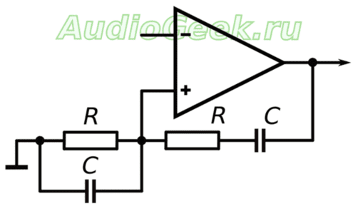
In fig. 1 shows a generator that produces a low distortion sinusoidal signal with the ability to control the output signal power. The high-power generator consists of two main parts: a double T-bridge circuit and a high-power, low-dropout regulator. The double T-bridge circuit works like two T-type filters connected in parallel: a low-pass filter and a high-pass filter.
The double T-bridge circuit has high frequency selectivity as a notch filter. The low dropout regulator amplifies the signal and controls the load. The regulator used in this circuit contains an internal reference current source with a voltage follower. The gain from the Set pin to the Out pin is one, and the current source is a 10 µA stable current source. The RSET resistor connected to the Set pin programs the DC voltage output level. Connecting a double T-bridge circuit between the Out and Set pins, causing the filter to attenuate both high and low frequencies, leads to the fact that a signal with a frequency corresponding to resonant frequency filter, passes through it unhindered. Resistors and capacitors set the center frequency of the filter, f0: f0 = 1 / (2πRC).
Small signal analysis of the double T-bridge circuit shows that the maximum gain is observed at the center frequency. The maximum generator gain on a double T-bridge increases from 1 to 1.1 as the K-factor increases from two to five (Fig. 2). The maximum gain decreases when the K-factor is greater than 5. Therefore, it is common to select a K-factor between three and five to achieve a gain greater than unity. Loop gain must be equal to unity to maintain stable oscillation. Thus, a potentiometer is required to trim the loop gain and control the output signal amplitude.

The generator based on the double T-bridge can drive inductive, capacitive and resistive load... The current limitation of the low dropout regulator, which is 1.1 A for the Linear Technology LT3080, is the only limitation on the generator's load control capability. The load characteristics, in turn, limit the frequency range. For example, a 10 ohm load with an output capacitor of 4.7 μF results in a THD of 7% at frequencies above 8 kHz, while at 400 Hz Kg is only 0.1% for the circuit in Fig. 3. The generator on the double T-bridge has the same linear load control performance as the LT3080 itself. In addition, it works over a wide temperature range.

Using automatic gain control, it is possible to replace the potentiometer with an incandescent lamp (Figure 3) or a voltage controlled channel of a MOSFET (Figure 4). The resistance of the incandescent lamp increases as the generator's output signal amplitude increases, resulting in a self-heating effect, thus tracking the gain that controls the generation of the output signal. In fig. 4, by detecting the peak value of the output voltage using a zener diode, the channel resistance of the MOSFET decreases as the oscillator output signal amplitude increases. Loop gain is also reduced by controlling signal generation.

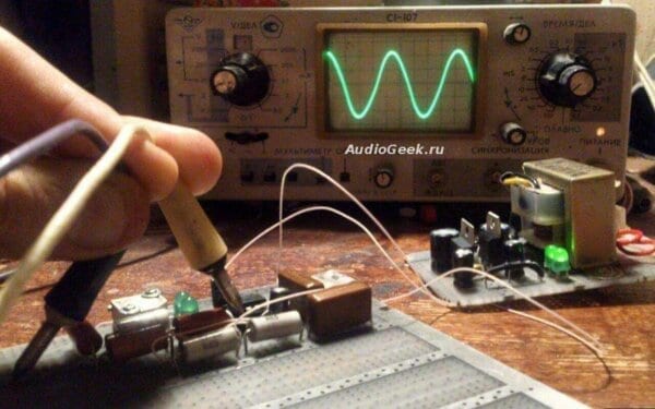
In fig. 5 shows a test of the waveform of a generator on a double T-bridge using an incandescent lamp. The output is tuned to a peak-to-peak 4V peak-to-peak signal at 5VDC bias (Figure 6). The generator on a double T-bridge has a generation frequency of 400 Hz and a harmonic distortion of Kg 0.1%. the most significant contribution comes from the second harmonic, which has an amplitude of less than 4 mV peak-to-peak. In fig. 6 shows a test of the waveform of a double T-bridge oscillator using a MOSFET. Kg was 1% at a second harmonic amplitude of 40 mV peak-to-peak.


Power-on transients are different important aspect generator. In both schemes, there are no ultra-low frequency oscillations characteristic of other types of generators. Signal shapes in Fig. 7 and fig. 8 indicates low turn-on overshoot. An oscillator using MOSFET stabilization is faster than an oscillator using incandescent lamp stabilization, since an incandescent lamp has a greater inertia with temperature changes.


This circuit can be used as a DC voltage controlled source alternating voltage in applications requiring low distortion and the ability to control output power.
Sinusoidal oscillator easy to assemble on an operational amplifier. The figure shows circuit diagram such a generator producing a signal with a frequency of 400 Hz.
Packets of rectangular pulses with a given number of pulses in a packet, it is convenient to use when debugging digital devices.
In amateur radio practice, it is often necessary frequency dividers with high division ratio(1000 ... 10000 and higher). Usually, for this, either 4-5 counters-dividers by 10 are used, or the K561IE15 microcircuit.
The generator, the diagram of which is shown in Fig. 1, can be used in various converters single-phase voltage to three-phase. It is simpler than those described in.
The undoubted advantage of the proposed scheme is its simplicity. Despite its unusual appearance, the scheme is quite reliable, the author has been using it for about 2 years.
Adjustable square wave generator
This device will find application in various automation devices for intermittent current interruption in load circuits or for generating pulses with widely variable period of repetition and duration. Pulse duty ratio can reach several thousand, the period of their repetition and duration - tens of seconds.
Create uncomplicated sine wave generator operating at sufficiently high frequencies is not an easy task. Well-known generators with a Wien bridge make it possible to generate oscillations with a frequency of no more than 1 MHz, and even then when using high-speed operational amplifiers of the K544, K574 series and with an output level of no more than 50 ... 100 mV.
The figure shows simple crystal oscillator circuit that can be collected on any logical element"AND - NOT", which is part of any microcircuit of the K155 series.
This simple device is voltage controlled generator (VCO). It can be used to audibly indicate the magnitude of a constant voltage in a tone of varying frequency. The basis of the VCO (see diagram) is the DA1 integrator and the Schmitt trigger on the elements DD1.1, DD1.2.
The generator (see illustration) provides a sawtooth voltage with good linearity.
Transistor T1 generator with resistor R1 in the emitter circuit, it is a current source with an output resistance equal to several megohms. The current of this source charges the capacitor C2.
Functional generator can be assembled on a special IC 8038 microcircuit. ICL8038 is an integrated circuit capable of producing sinusoidal, rectangular, triangular, sawtooth pulses. For fully functional work generator microcircuits the minimum number of external components is required.
Signal generators are devices primarily designed to test transmitters. Additionally, experts use them to measure the characteristics of analog converters. Testing of model transmitters is carried out by simulating a signal. This is necessary to check that the device complies with current standards. A signal can be sent directly to the device in pure form or with distortion. Its speed across channels can vary greatly.
What does a generator look like?
If we consider a conventional model of a signal generator, then a screen can be seen on the front panel. It is necessary in order to monitor fluctuations and control. At the top of the screen is an editor that offers a choice of various functions... Further below is the SevenSor, which shows the oscillation frequency. The mode line is located under it. The amplitude or offset level of the signal can be adjusted using two buttons. There is a separate mini-panel for working with files. With its help test results can be saved or immediately opened.
In order for the user to be able to change the sampling rate, the generator has a special regulator. Numerical values can be used to synchronize fairly quickly. Signal outputs are usually located at the bottom of the device, below the screen. There is also a button for starting the generator.
Homemade devices
Making a signal generator with your own hands is quite problematic due to the complexity of the device. The selector is considered to be the main piece of equipment. It is designed in the model for a certain number of channels. As a rule, there are two microcircuits in the device. The oscillator needs a synthesizer to adjust the frequency. If we consider multichannel devices, then microcontrollers for them are suitable for the KN148 series. Converters are used only of the analog type.
Sinusoidal signal devices
The sine wave generator of the microcircuit uses a fairly simple one. In this case, amplifiers can only be used of an operational type. This is necessary for normal signal transmission from the resistors to the board. Potentiometers are included in the system with a nominal value of at least 200 Ohm. The indicator of the duty cycle of the pulses depends on the speed of the generation process.
For flexible configuration of the device, multichannel units are installed. the sine wave generator is changed by means of the rotary control. For testing receivers, it is only suitable for the modulating type. This suggests that the generator should have at least five channels.

Low frequency generator circuit
The low frequency signal generator (schematic shown below) includes analog resistors. Potentiometers should only be set to 150 ohms. To change the pulse value, modulators of the KK202 series are used. Generation in in this case going through capacitors. There must be a jumper between the resistors in the circuit. The presence of two terminals allows a (low frequency) switch to be installed in the signal generator.

How the Beep Model Works
When connecting the frequency generator, initially the voltage is applied to the selector. Further alternating current passes through a bunch of transistors. After conversion, capacitors are turned on. The vibrations are reflected on the screen using a microcontroller. To adjust the cutoff frequency, special pins on the microcircuit are required.
The maximum output power in this case is the generator sound signal can reach 3 GHz, but the error should be minimal. For this, a limiter is installed near the resistor. Phase noise is picked up by the system through the connector. The phase modulation index depends solely on the current conversion rate.
Mixed signal circuit diagram
Standard scheme This type of generator has a multi-channel selector. In this case, there are more than five outputs on the panel. In this case, the maximum frequency can be set at 70 Hz. Capacitors in many models are available with a maximum capacitance of 20 pF. Resistors are most often turned on with a nominal value of 4 ohms. The setting time for the first mode is 2.5 s on average.
Due to the presence of a transmission limiter, the reverse power of the unit can reach 2 MHz. The frequency of the spectrum in this case can be adjusted using a modulator. Separate outputs are available for the output impedance. the level in the circuit is less than 2 dB. Converters to standard systems there are PP201 series.

Arbitrary Waveform Tool
These devices are designed for small errors. A flexible sequence mode is provided in them. The standard selector scheme has six channels. The minimum frequency setting is 70 Hz. Generator positive pulses of this type are perceived. The capacitors in the circuit have a capacity of at least 20 pF. The device can handle the output impedance up to 5 ohms.
In terms of synchronization parameters, these signal generators are quite different. This is due, as a rule, to the type of connector. As a result, the rise time ranges from 15 ns to 40 ns. There are two modes in the models (linear and logarithmic). With their help, the amplitude can be changed. The frequency error in this case is less than 3%.
Modifications to complex signals
To modify complex signals, specialists use only multichannel selectors in generators. They are equipped with amplifiers without fail. Regulators are used to change operating modes. Thanks to the converter, the current becomes constant from 60 Hz. The rise time should be no more than 40 ns on average. For this purpose, the minimum capacitance of the capacitor is 15 pF. The resistance of the system for the signal must be perceived in the region of 50 ohms. Distortion at 40 kHz is typically 1%. Thus, generators can be used to test receivers.
Generators with built-in editors
Signal generators of this type are very easy to set up. The regulators in them are designed for four positions. Thus, the level of the cut-off frequency can be adjusted. If we talk about the installation time, then in many models it is 3 ms. This is achieved through microcontrollers. They are connected to the board using jumpers. Bandwidth limiters are not installed in this type of generator. Converters according to the device diagram are located behind the selectors. Synthesizers are rarely used in models. The maximum output power of the device is at 2 MHz. The error in this case is allowed only 2%.

Devices with digital outputs
Signal generators with digital outputs and connectors are equipped with the KR300 series. Resistors, in turn, are switched on with a nominal value of at least 4 ohms. Thus, the internal resistance of the resistor is kept high. Receivers with a power of no more than 15 V are capable of testing these devices. Connection to the converter is carried out only through jumpers.
Selectors in generators can be found in three- and four-channel. The microcircuit in a standard circuit, as a rule, is of the KA345 type. Gauge switches use rotary switches only. Pulse modulation in generators occurs rather quickly, and this is achieved due to a high transmission coefficient. Also consider the low broadband noise level of 10 dB.
High Clock Models
The high-frequency signal generator is powerful. Internal resistance, it is able to withstand an average of 50 ohms. The bandwidth for such models is usually 2 GHz. Additionally, it should be borne in mind that capacitors are used with a capacity of at least 7 pF. Thus, the maximum current is maintained at 3 A. The distortion in the system can be a maximum of 1%.
Amplifiers, as a rule, can be found in generators only of the operational type. Limiters in the chain are installed at the beginning, as well as at the end. A connector for selecting the type of signals is present. Microcontrollers can be found most often of the RRK211 series. The selector is designed for at least six channels. Rotary regulators in such devices are available. The maximum cut-off frequency can be set at 90 Hz.

Operation of logic signal generators
This signal generator resistors are rated no more than 4 ohms. At the same time, the internal resistance is kept quite high. To reduce the signal transmission rate, types are set. As a rule, there are three pins on the panel. The connection to the bandwidth limiters is made only through jumpers.
The switches in the devices are rotary. There are two modes to choose from. Signal generators of this type may be used for phase modulation. Their broadband noise parameter does not exceed 5 dB. Frequency deviation is usually around 16 MHz. The disadvantages include a long rise and fall times. This is due to the low throughput microcontroller.

Generator circuit with modulator MX101
The standard generator circuit with such a modulator provides for a selector for five channels. This makes it possible to work in a linear mode. The maximum amplitude at low load is maintained at 10 peak. DC offset is rare. The output current parameter is at around 4 A. The frequency error is maximum capable of reaching 3%. The average rise time for oscillators with such modulators is 50 ns.
The meander waveform is perceived by the system. You can test receivers using this model with a power of no more than 5 V. The logarithmic sweep mode allows you to work quite successfully with various measuring instruments. The tuning speed on the panel can be changed smoothly. Due to the high output resistance, the load is removed from the converters.
The generator of various stable frequencies is a necessary laboratory equipment. There are many on the Internet circuits, but they are either morally outdated, or do not provide a sufficiently wide frequency coverage. The device described here is based on the high quality performance of an ASIC XR2206... The range of frequencies overlapped by the generator is impressive: 1 Hz - 1 MHz!XR2206is capable of generating high-quality sine, rectangular and triangular waveforms of high accuracy and stability. The output signals can have both amplitude and frequency modulation.
Generator parameters
Sinusoidal signal:
Amplitude: 0 - 3V with 9V supply
- Distortion: less than 1% (1 kHz)
- Flatness: +0.05 dB 1 Hz - 100 kHz
Square wave:
Amplitude: 8V with 9V supply
- Rise time: less than 50 ns (at 1 kHz)
- Fall time: less than 30 ns (at 1 kHz)
- Unbalance: less than 5% (1 kHz)
Triangle signal:
Amplitude: 0 - 3V with 9V supply
- Non-linearity: less than 1% (up to 100 kHz)
Schemes and PP


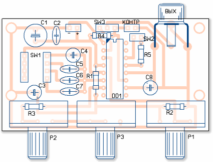
Drawings of printed circuit boards
Coarse frequency control is carried out using a 4-position switch for frequency ranges; (1) 1 Hz-100 Hz, (2) 100 Hz-20 kHz, (3) 20 kHz-1 MHz (4) 150 kHz-1 MHz. Despite the fact that the upper limit of 3 megahertz is indicated in the circuit, the guaranteed limiting frequency is exactly 1 MHz, then the generated signal may be less stable.
In amateur radio practice, it is often necessary to use a sinusoidal oscillator. It can be used in a variety of ways. Let's consider how to create a sinusoidal signal generator on the Wien bridge with stable amplitude and frequency.
This article describes the design of a sine wave generator circuit. You can also generate the desired frequency programmatically:
The most convenient, from the point of view of assembly and commissioning, a variant of a sinusoidal signal generator is a generator built on the Wien bridge, on a modern Operational Amplifier (OA).
Bridge of Wine
The Wien Bridge itself is a band pass filter consisting of two. It emphasizes the center frequency and suppresses the rest of the frequencies.
The bridge was invented by Max Wien back in 1891. In a schematic diagram, the Wien Bridge itself is usually depicted as follows:
Image borrowed from Wikipedia
The Wien bridge has the ratio of the output voltage to the input voltage b = 1/3 ... This important point, because this coefficient determines the conditions for stable generation. But more on that later
How to calculate the frequency
Oscillators and inductance meters are often built on the Wien Bridge. In order not to complicate their life, they usually use R1 = R2 = R and C1 = C2 = C ... This can simplify the formula. The fundamental frequency of the bridge is calculated from the ratio:
f = 1 / 2πRC
Almost any filter can be thought of as a frequency-dependent voltage divider. Therefore, when choosing the values of the resistor and capacitor, it is desirable that at the resonant frequency the complex resistance of the capacitor (Z) be equal, or at least of the same order of magnitude, with the resistance of the resistor.
Zc = 1 / ωC = 1 / 2πνC
where ω (omega) - cyclic frequency, ν (nu) - line frequency, ω = 2πν
Wine Bridge and Operational Amplifier
The Wien Bridge itself is not a signal generator. For generation to occur, it should be placed in a positive circuit. feedback operational amplifier. Such an autogenerator can also be built on a transistor. But using an op amp will clearly make life easier and give better performance.
Gain of C grade
The Wine Bridge has a transmittance b = 1/3 ... Therefore, the condition for generation is that the op-amp must provide a gain of three. In this case, the product of the transmission coefficients of the Wien bridge and the gain of the op-amp will give 1. And there will be a stable generation of the specified frequency.
If the world were ideal, then setting the required gain by the resistors in the negative feedback circuit, we would get a ready-made generator.

It is a non-inverting amplifier and its gain is given by:K = 1 + R2 / R1
But alas, the world is not perfect. ... In practice, it turns out that to start generation it is necessary that at the very initial moment the coeff. gain was slightly more than 3, and then for stable generation it was kept equal to 3.
If the gain is less than 3, then the generator will stall, if more, then the signal, having reached the supply voltage, will begin to distort, and saturation will occur.
At saturation, the output will maintain a voltage close to one of the supply voltages. And random chaotic switching between supply voltages will occur.

Therefore, when building an oscillator on the Wien bridge, they resort to using a nonlinear element in the negative feedback circuit that regulates the gain. In this case, the generator will balance itself and maintain the generation at the same level.
Amplitude stabilization on an incandescent lamp
In the most classic version of the generator on the Wien bridge on the op-amp, a miniature low-voltage incandescent lamp is used, which is installed instead of a resistor.

When you turn on such a generator, at the first moment, the lamp spiral is cold and its resistance is small. This helps to start the generator (K> 3). Then, as it heats up, the resistance of the coil increases and the gain decreases until it reaches equilibrium (K = 3).
The positive feedback loop in which the Wien bridge was placed remains unchanged. The general schematic diagram of the generator is as follows:

The op-amp's positive feedback elements determine the oscillation frequency. And the elements of negative feedback are amplification.
The idea of using a light bulb as a control element is very interesting and is used to this day. But the light bulb, alas, has a number of disadvantages:
- selection of a light bulb and a current-limiting resistor R * is required.
- with regular use of the generator, the life of a light bulb is usually limited to a few months
- the control properties of the light bulb depend on the temperature in the room.
Another interesting option is the use of a direct fired thermistor. In fact, the idea is the same, only a thermistor is used instead of a bulb spiral. The problem is that you need to find it first and again pick it up and the current-limiting resistors.
Amplitude stabilization on LEDs
An effective method for stabilizing the amplitude of the output voltage of a sinusoidal signal generator is the use of an op-amp LED ( VD1 and VD2 ).

The main gain is set by resistors R3 and R4 ... The rest of the elements ( R5 , R6 and LEDs) adjust the gain in a small range, keeping the generation stable. Resistor R5 you can adjust the value of the output voltage in the range of approximately 5-10 volts.
In the additional OS circuit, it is advisable to use low-resistance resistors ( R5 and R6 ). This will allow a significant current (up to 5mA) to pass through the LEDs and they will be in optimal mode. They will even glow a little :-)
In the diagram shown above, the elements of the Wien bridge are designed to generate at a frequency of 400 Hz, however, they can be easily recalculated for any other frequency using the formulas presented at the beginning of the article.
Quality of generation and applied elements
It is important that the op-amp can provide the current required for generation and has sufficient frequency bandwidth. The use of the folk TL062 and TL072 as an op-amp gave very sad results at a generation frequency of 100 kHz. It was difficult to call the waveform sinusoidal; rather, it was a triangular waveform. Using TDA 2320 gave an even worse result.
But the NE5532 shows itself from an excellent side, producing a signal at the output that is very similar to a sinusoidal one. LM833 also coped with the task perfectly. So it is NE5532 and LM833 that are recommended for use as affordable and widespread high-quality op amps. Although with decreasing frequency, the rest of the op amps will feel much better.
The accuracy of the generation frequency directly depends on the accuracy of the elements of the frequency-dependent circuit. And in this case, it is not only the correspondence of the denomination of the element of the inscription on it that is important. More accurate parts have better value stability with temperature changes.
In the author's version, a C2-13 resistor ± 0.5% and mica capacitors with an accuracy of ± 2% were used. The use of resistors of this type is due to the small dependence of their resistance on temperature. Mica capacitors also depend little on temperature and have a low TKE.
Cons of LEDs
It is worth dwelling on LEDs separately. Their use in a sine generator circuit is caused by the magnitude of the voltage drop, which usually lies in the range of 1.2-1.5 volts. This makes it possible to obtain a sufficiently high value of the output voltage.
After the implementation of the circuit, on a breadboard, it turned out that due to the scatter of the LED parameters, the edges of the sinusoid at the generator output are not symmetrical. It is a little noticeable even in the above photo. In addition, there were slight distortions in the generated sine shape caused by the insufficient speed of the LEDs for the generation frequency of 100 kHz.
Diodes 4148 instead of LEDs
The LEDs have been replaced by everyone's favorite 4148 diodes. These are affordable high speed signal diodes with switching speeds of less than 4 ns. At the same time, the circuit remained fully functional, there was no trace of the problems described above, and the sinusoid acquired an ideal form.
In the following diagram, the elements of the wine bridge are rated for an oscillation frequency of 100 kHz. Also, the variable resistor R5 was replaced with constant ones, but more on that later.

Unlike LEDs, the voltage drop across p-n junction conventional diodes is 0.6 ÷ 0.7 V, so the output voltage of the generator was about 2.5 V. To increase the output voltage, it is possible to connect several diodes in series, instead of one, for example, like this:

However, increasing the number of non-linear elements will make the generator more dependent on external temperature. For this reason, it was decided to abandon this approach and use one diode each.
Replacing a variable resistor with constants
Now about the trimmer. Initially, a 470 ohm multiturn trimmer resistor was used as resistor R5. It made it possible to precisely control the value of the output voltage.
When building any generator, it is highly desirable to have an oscilloscope. The variable resistor R5 directly affects the generation - both the amplitude and the stability.
For the presented circuit, generation is stable only in a small range of resistances of this resistor. If the resistance ratio is greater than the required one, clipping starts, i.e. the sine wave will be clipped at the top and bottom. If less, the shape of the sinusoid begins to distort, and with a further decrease, the generation stalls.
It also depends on the supply voltage used. The described circuit was originally assembled on an LM833 op-amp with a ± 9V supply. Then, without changing the circuit, the op amps were replaced with an AD8616, and the supply voltage was ± 2.5V (maximum for these op amps). As a result of such a replacement, the sinusoid at the output was cut off. The selection of resistors gave values of 210 and 165 ohms, instead of 150 and 330, respectively.
How to choose resistors "by eye"
In principle, you can leave the trimmer resistor as well. It all depends on the required accuracy and the generated sine signal frequency.
For self-selection, you should, first of all, install a trimming resistor with a nominal value of 200-500 Ohm. By applying the generator output signal to the oscilloscope and turning the trimmer resistor, reach the moment when the limitation begins.
Then, lowering the amplitude, find the position in which the shape of the sinusoid will be the best. Now you can unsolder the trimmer, measure the resulting resistance values and solder as close as possible.
If you need an audio sine wave generator, you can do without an oscilloscope. To do this, again, it is better to reach the moment when the signal, by ear, begins to distort due to clipping, and then reduce the amplitude. It should be reduced until the distortion disappears, and then a little more. This is necessary because by ear it is not always possible to catch distortions even in 10%.
Additional reinforcement
The sine generator was assembled on a dual op-amp, and half of the microcircuit was left hanging in the air. Therefore, it is logical to use it under an adjustable voltage amplifier. This made it possible to transfer the variable resistor from the additional circuit of the oscillator OS to the voltage amplifier stage to adjust the output voltage.
Application of additional amplifier stage guarantees a better match of the generator output to the load. It was built according to the classic non-inverting amplifier circuit.
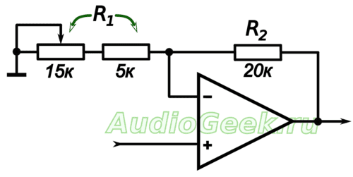
The indicated ratings allow you to change the gain from 2 to 5. If necessary, the ratings can be recalculated for the required task. The gain of the stage is set by the ratio:
K = 1 + R2 / R1
Resistor R1 is the sum of series-connected variable and constant resistors. A constant resistor is needed so that the gain does not go to infinity at the minimum position of the variable resistor knob.
How to empower the exit
The generator was supposed to operate on a low-impedance load of several ohms. Of course, no low-power op-amp will be able to deliver the required current.
For powering up, a repeater on the TDA2030 is located at the generator output. All the goodies of this application of this microcircuit are described in the article.
And this is how the circuit of the entire sinusoidal generator with a voltage amplifier and a follower at the output actually looks like:

The sine generator on the Wien bridge can be assembled on the TDA2030 itself as an op amp. It all depends on the required accuracy and the selected frequency of generation.
If there are no special requirements for the quality of generation and the required frequency does not exceed 80-100 kHz, but it is supposed to work on a low-impedance load, then this option is ideal for you.
Conclusion
A Wien bridge generator is not the only way to generate a sinusoid. If you need high-precision frequency stabilization, it is better to look towards oscillators with a quartz resonator.
However, the described scheme is suitable for the vast majority of cases when it is required to obtain a stable, both in frequency and amplitude, sinusoidal signal.
Generation is good, but how to accurately measure the magnitude of the high frequency AC voltage? For this, a circuit called.
Material prepared exclusively for the site


