If you want to assemble a long-range WiFi antenna, then you should know about some of its features.
First and most simple: large antennas of 15 or 20 dBi (isotropic decibels) are power-limiting and don't need to be made more powerful.
Here is a clear illustration of how with an increase in the antenna power in dBi, its coverage area decreases.
So it turns out that with an increase in the distance of the antenna, the area of its coverage is significantly reduced. At home, you will have to constantly catch a narrow band of signal activity with a too powerful WiFi emitter. Get up off the couch or lie down on the floor, and the connection will immediately disappear.
This is why home routers have conventional, all-round, 2dBi antennas - so they are most effective over short distances.
Directional
9 dBi antennas work only in a given direction (directional action) - they are useless in a room, they are best used for long distance communication, in the yard, in the garage next to the house. The directional antenna during installation will need to be adjusted to transmit a clear signal in the desired direction.
Now to the question of the carrier frequency. Which antenna will work best at long range, 2.4 GHz or 5 GHz?
Now there are new routers operating at a doubled frequency of 5 GHz. These routers are still new, they are good for high-speed data transfer. But the 5 GHz signal is not very good for long distances, as it decays faster than the 2.4 GHz signal.
Therefore, old 2.4 GHz routers will perform better in long-range mode than new high-speed ones at 5 GHz.
Blueprint of a double homemade biquadrat
The first samples of self-made distributors of WiFi signal appeared back in 2005.
The best of these are biquadratic designs that provide up to 11–12 dBi gain and double biquadratic designs that have a slightly better result at 14 dBi.
According to the experience of use, the biquadrat design is more suitable as a multifunctional emitter. Indeed, the advantage of this antenna is that with the inevitable compression of the radiation field, the signal opening angle remains wide enough to cover the entire area of the apartment when correctly installed.
All possible versions of the biquad antenna are easy to implement. 
Required details
- Metal reflector - a piece of foil-coated textolite 123x123 mm, a sheet of foil, CD, DVD compact disc, an aluminum lid with a tea can.
- Copper wire with a cross section of 2.5 mm2
- A piece of coaxial cable, preferably with wave impedance 50 Ohm.
- Plastic tubes - can be cut from a ballpoint pen, felt-tip pen, marker.
- Some hot melt glue.
- N-type connector - useful for convenient antenna connection.
For the 2.4 GHz frequency on which the transmitter is planned to be used, the ideal size of the biquad is 30.5 mm. But all the same, we do not make a satellite dish, therefore, some deviations in the dimensions of the active element -30–31 mm are permissible.
The question of the thickness of the wire also needs to be considered carefully. Taking into account the selected frequency of 2.4 GHz, the copper core must be found with a thickness of exactly 1.8 mm (with a cross section of 2.5 mm2).
From the edge of the wire we measure the distance of 29 mm to the bend.
We make the next bend, checking the outer dimension of 30–31 mm.
The next inward folds are made at a distance of 29 mm.
We check the most important parameter for the finished biquadrat -31 mm along the midline.
We solder the places for the future fastening of the coaxial cable leads.
Reflector
The main task of the iron shield behind the emitter is to reflect electromagnetic waves. Correctly reflected waves will superimpose their amplitudes on the vibrations just released by the active element. The resulting amplifying interference will make it possible to spread the electromagnetic waves from the antenna as far as possible.
To achieve useful interference, the emitter must be positioned at a multiple of a quarter wavelength from the reflector.
Distance from emitter to reflector for antennas, the biquadrat and double biquadrat are found as lambda / 10 - determined by the features of this design / 4.
Lambda is a wavelength equal to the speed of light in m / s divided by the frequency in Hz.
The wavelength at a frequency of 2.4 GHz is 0.125 m.
Increasing the calculated value fivefold, we get optimal distance - 15.625 mm.
Reflector size affects the antenna gain in dBi. Optimal dimensions the screen for the biquadrat is 123x123 mm or more, only in this case it is possible to achieve a gain of 12 dBi.
The size of CD and DVD discs is clearly not enough for full reflection, therefore biquadratic antennas built on them have a gain of only 8 dBi.
Below is an example of using a tea can lid as a reflector. The size of such a screen is also not enough, the antenna gain is less than expected.
Reflector shape should only be flat. Also try to find the plates as smooth as possible. Bends, scratches on the screen lead to scattering of high-frequency waves, due to the violation of reflection in a given direction.
In the above example, the sides on the lid are clearly superfluous - they reduce the signal opening angle, create diffused interference.
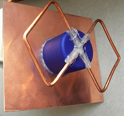
Once the reflector plate is ready, you have two ways to assemble the emitter on it.
- Install copper tube by soldering.
To fix the double biquadrat, it was necessary to additionally make two racks from a ballpoint pen.
- Fix everything on a plastic tube using hot melt glue.
We take a plastic box for discs for 25 pieces.
Cut off the central pin, leaving 18 mm in height.
We cut with a file or a file four slots in a plastic pin.
We trim the splines equally in depth
We install a homemade frame on the spindle, check that its edges are at the same height from the bottom of the box - about 16 mm.
We solder the cable leads to the emitter frame.
Taking a glue gun, we fix the CD to the bottom with the plastic box.
We continue to work with a glue gun, fix the emitter frame on the spindle.
On the back of the box, fix the cable with hot glue.
Connecting to a router
Anyone with experience can easily solder to the contact pads on the circuit board inside the router.
Otherwise, be careful, thin tracks may come off the printed circuit board during long-term heating with a soldering iron.
You can connect to the already soldered piece of the native antenna cable through the SMA connector. There should be no problem purchasing any other N-type RF connector at your nearest electronics retailer.
Antenna tests
Tests have shown that an ideal biquadrat gives a gain of about 11-12 dBi, which is up to 4 km of directional signal.
The antenna from the CD disc gives 8 dBi, since it turns out to pick up the WiFi signal at a distance of 2 km.
The double biquadrat provides 14dB - slightly over 6km.
The opening angle of antennas with a square radiator is about 60 degrees, which is quite enough for a courtyard of a private house.
About the range of the Wi-Fi antenna
From a native 2 dBi router antenna, the 2.4 GHz signal, the 802.11n standard, can extend up to 400 meters in line of sight. Signals 2.4 GHz, old standards 802.11b, 802.11g propagate worse, having half the range compared to 802.11n.
Considering a WiFi antenna as an isotropic emitter - an ideal source that spreads electromagnetic energy evenly in all directions, you can use the logarithmic formula for converting dBi to power gain.
Isotropic decibel (dBi) is the antenna gain, defined as ten times the decimal algorithm of the ratio of the amplified electromagnetic signal to its original value.
AdBi = 10lg (A1 / A0)
Converting dBi antennas to power gain.
| A, dBi | 30 | 20 | 18 | 16 | 15 | 14 | 13 | 12 | 10 | 9 | 6 | 5 | 3 | 2 | 1 |
| A1 / A0 | 1000 | 100 | ≈64 | ≈40 | ≈32 | ≈25 | ≈20 | ≈16 | 10 | ≈8 | ≈4 | ≈3.2 | ≈2 | ≈1.6 | ≈1.26 |
Judging by the table, it is easy to conclude that a directional WiFi transmitter with a maximum allowable power of 20 dBi can spread a signal over a distance of 25 km in the absence of obstacles.
The popularity of the Internet among the population is constantly growing. However, many people live in areas where there is very little or no signal at all. In this regard, the problem of increasing the power and quality of Internet reception is very acute. Slow speed is time consuming and does not give the desired result. Therefore, an external Kharchenko antenna often comes to the rescue, designed in a form, for which a thick copper wire serves as a material. The connection with a square to each other occurs in places of open corners, where the television cable is connected.
Such an antenna requires an accurate calculation for digital terrestrial television... To improve directivity, some designs can be equipped with a grating or solid screen made of conductive material. Such a biquad antenna can solve many problems with signal reception and Internet speed. Homemade designs that include Various types Kharchenko's antennas are relatively easy to make and include metal and plastic parts, as well as elements made of other materials that are connected different ways... Such structures are easily made independently, including the Kharchenko's antenna for TV with their own hands.
Kharchenko antenna for modem
Nowadays, many users are looking to increase the speed of their mobile internet... This problem is especially acute for those who live at a considerable distance from the base station, using the Internet at a very low speed. In such situations, the best way out is the Kharchenko antenna for a 3g modem with your own hands, which is quite easy to make at home.
This frame design has been known as the UHF antenna since the 60s of the last century. It has a zigzag frame configuration, which makes the device very efficient.
The system consists of two square elements. In order to calculate the antenna for a 3g modem at a frequency of 2100 MHz, the size of each side of the square should be 53 mm. The whole structure is made in the form of an interlocking structure, which includes two diamond-shaped figures with internal corners 1200. This is done in order to reduce the internal resistance of the device. The connection of the rhombuses is carried out with each other by soldering. A high-frequency cable is also soldered here in the future.
More accurate data can be obtained using online calculator to calculate the Kharchenko antenna, in which it is enough just to enter the necessary initial data.
To increase efficiency, the device can be used in conjunction with a reflector. Usually this part is a metal plate, and the most suitable material for its manufacture is foil-coated textolite. V in this case Antenna includes determining the distance between the receiving device and the reflector. After calculations and procurement of materials, a Kharchenko antenna for a modem can be made by hand.
The connection of parts to each other is carried out using hot melt glue. You can fix the required distance between the elements using any object with the most suitable dimensions. Then the antenna is connected to the device. Since the modems do not have connectors for connecting external antennas, they are simply wrapped with wire, which is then connected via a cable to the receiving device. If necessary, a Kharchenko antenna for a 4g modem can be made according to the same scheme.
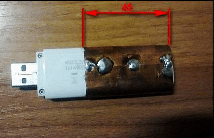
At the end of the assembly, at the opposite end of the cable, which will be connected to the modem, you need to assemble the so-called matching device, provided specifically for such devices. For this purpose, copper foil is used, the same as in printed circuit boards... The performed antenna calculation for a 4g modem is the same as in the previous version.
If there is a connector for an external antenna, the cable is connected using a special adapter. After all connections, the antenna for the modem is considered ready for use. Signal reception tuning for 4g is performed experimentally by slowly rotating the structure around the axis until the clearest signal is obtained. The signal quality is determined by the number of dashes on the icon displayed on the computer or mobile phone.
Kharchenko antenna for digital TV
For work digital television the decimeter wavelength range is used. Therefore, before designing, Kharchenko antennas for DVB t2 should be completed in order to maximize signal reception.
The design itself looks quite compact, it is made in the classic version of two rhombuses, as a result, a zigzag antenna without a reflector is obtained. Any conductive material can be used as a base, for example, copper or aluminum conductor, 1-5 mm in diameter. Tubes, strips, corners, profiles, etc. are also suitable. Copper wire with a thickness of 3 mm is best suited for this purpose. It is very easy to bend, align and solder. Further, it must be made in a certain sequence. The resistance of the TV cable should be approximately 50-75 ohms.

The quality of the digital signal does not depend on the distance, as is the case with analog television. In this case, when the antenna for TV is working normally, the signal normally enters the TV receiver, but if there are failures, then there will be no signal at all. Accordingly, there will be no image either. If there is a signal and it is received normally, then the image will be of the same quality on all channels. This factor must be taken into account when performed for digital TV, although individual settings may be different for a particular region.
Directly, the Kharchenko television antenna is manufactured in a specific sequence:
- First, you need to measure a piece of wire with a total length of 112 cm and bend it, observing the dimensions of the sections alternately 13 and 14 cm.
- After all the bends, two ends are formed, which must be cleaned at a distance of 1.5-2 cm. Loops are made at the ends and fixed to each other. The joints are completely sealed. Then, the central core is soldered to one of the joints, and the braid is soldered to the other. The result is a finished antenna or double square.
- A biquad TV antenna requires a TV cable of about 3 meters. From the side of the antenna, it is stripped by 2 cm, and from the side of the plug - by 1 cm. The plug can be selected at your discretion. It, like the wire, must be cleaned with a file or some kind of sharp object. Thus, Kharchenko's zigzag antenna for digital TV is almost ready for use.
- At the end of the soldering, all joints should be filled with hot glue from a gun. While the glue has not cooled down, the excess must be collected. A reliable and flexible connection is obtained at the same time. On the antenna itself, the soldering points are also filled with glue.
Antenna Kharchenko for phone
A remote directional antenna can significantly increase the capabilities of a mobile phone and improve the quality of communication when a subscriber is in a remote area. It is not always possible to find the most suitable option on sale, therefore, the Kharchenko antenna for cellular, made from scrap materials with your own hands.

The most affordable option is the standard design discussed above. Such an antenna should be sized based on the specific operating conditions. All necessary materials are sold at the hardware store. The simplest designs can be directly connected to the cable and do not require any special settings.
First of all, you need to stock up on copper wire with a diameter of 2-3 mm. You can take an insulated wire and strip the insulation from it. If the connections will be made without soldering, special F-type antenna connectors and connectors will be required. When it is planned to connect two Kharchenko antennas in parallel, you may need a reflector, which can be tin or aluminum. The joints are insulated using heat shrink tubing or electrical tape. Soldering requires a soldering iron.
The copper wire, prepared in advance, is bent and turns into a zigzag frame, which is made up of two rhombuses. The sides of each of them are 80 cm long, and the total distance between the opposite corners will be 226 cm. Next, the antenna calculator determines the junction point of these diamonds as the junction with the cable. A piece of cable 50 cm in size is soldered to this point, and an F-type connector is screwed to its opposite end. Next, the main cable of the required length is connected to the connector.

In some cases, the calculation of the Kharchenko antenna online involves the installation of a reflector, which significantly enhances signal reception in a certain area. The design is the same as the antenna for t2, when the lower end of the frame and the reflector are connected to each other through the cable sheath. For this purpose, a 50 mm long bolt is additionally screwed into the reflector, to which the F-type connector is attracted by means of a tie. A cable and a frame located at a distance of more than 40 mm are pre-soldered to this connector. Thus, Kharchenko's antenna for a mobile phone, made independently in the simplest version, is ready for use.
For direct connection of the receiver to mobile phone a pigtail is used, which is a special wire. One end of it is connected to the antenna cable, and the other is connected using a connector with the telephone's antenna jack. In this case, there is no problem to calculate the antenna and no separate settings are required, it is enough just to position the antenna in the most optimal way, focusing on the quality of the received signal. It is recommended to install the mast with the receiving device as close to the house as possible, preferably near a window to minimize the cable length.
With the transition to digital television in the DVB-T2 format, the question often arises, which antenna to choose? We offer you to assemble the simplest UHF TV antenna "biquadrat" with your own hands, it is also called the Kharchenko antenna. It is assembled very quickly from available materials, while having decent characteristics comparable to factory indoor antennas which come with an amplifier.

To assemble a biquadrat TV antenna we need:
- Copper or aluminum wire, 3-5 mm in diameter;
- TV coaxial cable 75 Ohm;
- Soldering iron, tin, solder or flux;
- Pliers;
- Electrical tape or plastic ties;
- Thermal gun with glue stick;
- Plastic bottle cap (optional).
How to make a biquadrat TV antenna for T2 television, step by step instructions:
So, we take copper or aluminum wire, copper is better, since it is better soldered, soldering acid or flux for soldering aluminum is needed to solder aluminum. The type of the selected metal will not affect the quality of the reception in any way. We bend it in a zigzag manner as shown in the figure. In order to choose the right length of each side, there is a formula into which you need to insert the average broadcasting frequency of your stations, the receiving frequencies of digital television in your region are indicated on the digital TV website in your country. For example, in Kiev, the average broadcasting frequency is 576 MHz, in Moscow it is 522 MHz.
Now we insert this frequency into the formula: 300000 / your average frequency / 4 = side of the biquad in mm. The essence of the formula: we divide the speed of light by the average broadcasting frequency = we get the wavelength. For normal reception, divide the wavelength by 4 and get the side of the biquadrat. In my case, it turned out 135 mm, which means that the outer sides of the biquadrat will be 135 mm, and the inner sides 130 mm, since there should be a gap of about 10 mm in the middle of the antenna. That is, the two squares in the center should not overlap. If your wire is insulated, then it is not necessary to remove all the insulation, but only in the center, where the contacts from the cable will be soldered.


We take a soldering iron, preferably more powerful, for example, 100 W, a flux (better active), and the ends of the wire, in the place where they converged, we solder them (I started to bend the biquadrat from the middle of the antenna and therefore the solder will be in the same place) to get closed loop.
Now we take a coaxial antenna TV cable of the required length, we strip the end of the cable so that the central core peeps out of the insulation by 1 cm and the same amount of braid, the main thing is that the central core does not touch the braid, there is no short circuit. The braid can be twisted and tinned with flux and solder.
We solder the central core of the cable to the middle of the antenna to one of its sides, and the braid to the other side, as shown in the photo. Before that, you can twist these ends of the cable a little on the wire, for a more reliable attachment.


You can insert a plastic bottle cap into the center of the antenna, for greater reliability, put the cable and 4 outgoing antenna beams into it, cut all the necessary recesses and holes in it and fill everything inside the lid with hot glue. The cable can be run along one of the biquadrat antenna walls by pulling with ties or electrical tape.


It remains to attach a plug to the other end of the cable, plug the biquadrat antenna into the T2 prefix and try to receive the signal, while you need to find a place in the apartment where the signal will be the best and hang or put the antenna there.


Note that the biquadratic antenna must be positioned vertically, that is, the two squares must be on top of each other, not next to each other.
This article details the construction of a biquad antenna. The biquad antenna is easy to manufacture and provides a reliable 11dB gain, with a fairly wide beamwidth.
Trevor Marshall has a web page with information on using the biquad as an irradiator for satellite dish Primestar, with very good results. I decided to try using biquad as a 24dB illuminator parabolic antenna.
Note that the photos on Trevor Marshall's web site do not clearly show the construction of the biquad - especially the way the vibrator is connected to the cable. Many people (myself included) have constructed the biquads incorrectly based on his photographs, and have come to the conclusion that his performance is very poor.
Use the pictures of my biquad antenna shown below and refer to the websites listed in the reference section at the end of this page to obtain additional information about the correct construction of the biquad.
Materials used
I used the following materials:
- 123mmx123mm piece of foil-clad PCB
- 1/2 ″ diameter 50mm copper tube
- short length of CNT-400 or L MR-400 coaxial cable (~ 300mm)
- 250mm 2.5mm2 copper wire (approx 1.5mm diameter)
- N connector
Note that you are not required to use PCB for the reflector. You can use any electrically conductive material that reflects radio waves (that is, any metal plate).
I've also heard about people using a CD-ROM as a reflector because the foil on the disc reflects radio waves.
Reflector
Cut a 123 × 123 mm plate out of foil-clad textolite.

Cut a 50mm piece from the copper tube and polish it (including the inside to ensure good connection with cable).


Drill a hole in the PCB so that the resulting tube fits snugly in the hole. I found it most convenient to do this with a drill, having previously drilled a hole.

Insert the copper tube into the hole with the cutout on the copper side of the PCB. The copper pipe should protrude 16 mm from the hole.

Solder the copper tube to the PCB to get a good electrical connection.

To solder the tube, a sufficiently high power of the soldering iron is required. I have found a small gas burner to work well for this purpose.
Making a vibrator
The vibrator is made from a piece of copper wire bent into two squares.
Note that the lengths of each of the "sides" must be as accurate as possible (length is measured from the center of the copper wire to the center of the copper wire).

I used copper wire from a piece of 2.5mm 2 electrical cable. This cable is about 1.6mm in diameter, slightly more than the 1.2mm Trevor Marshall recommends. This should not have much effect on the performance of the antenna.

Remove the insulation, cut a 244mm length and straighten it well

Measure the center of the wire and make a 90 degree bend. The bending radius should be as small as possible.

Measure the middle of each half, and make two more 90-degree bends to form the shape shown in the photo below.

Measure the middle of each section again, and make another 90 degree bend so that you get the shape shown in the photo below.
 Another bend
 Do the same to the other side to shape the antenna into a biquad.

Check that each side is 30.5mm and flat. You may need to shorten the wire a little.
Assembly
The vibrator should now be attached to the reflector. Note that only two "ends" of the copper wire will be connected to the copper tube - the center of the copper wire must not touch the copper tube (This is where the cutout is required in the copper tube).
The vibrator wire should be at a distance of ~ 15 mm from the reflector. When testing the antenna, changing the spacing between the vibrator and the reflector, I got the result that the distance of ~ 15 mm provides the lowest SWR (test results are available here).

Strip the coaxial cable 30mm. 
Loosen the outer braid, strip the center conductor and cut it so that it protrudes 4mm outward

Insert the cable into the copper tube, so that the center core of the wire is flush with the end of the tube, and solder the center of the vibrator to it. Make sure the center of the vibrator does not touch the copper tube.


In order for the cable to hold firmly in the tube, it must be crimped with a cable crimper.


Now all that remains is to install the connector on the other end of the cable.
If desired, you can add spacers at the ends of the vibrator to increase mechanical strength. You can see how to do them on the page about the antenna.
If you are going to mount the biquad antenna outside, I would recommend that you place it in a weatherproof housing to prevent corrosion and water from entering the cable.
Many people successfully use microwave food containers for this purpose.
Testing
Conducted first testing of biquad antenna as feed for 24dB parabolic antenna. The results were quite satisfactory to me.
I also managed to get a connection at a distance of 10 km using only a biquad connected to a 30mW RoamAbout Wi-Fi card.
Some more detailed testing with multiple antennas, including the biquad shown above, indicates that the biquad has a gain of 11-12dB.
A friend has access to some antenna test equipment, and has performed some of the biquad tests shown on this page.
The biquad pattern shown below shows a beam width of ~ 50 degrees.

Variants
Many people suggest that the distance between the vibrator and the reflector should be 1/4 of the wavelength (that is, 30.5 mm) instead of 15 mm. However, the test results indicate that the SWR biquad is minimal when the distance between vibrator and reflector is 15-17mm. Increasing the spacing to 30.5 mm increases the SWR, thus decreasing the effectiveness of the biquad.
If you need more antenna efficiency, you can use an antenna that is just as easy to manufacture.
Usage
When using a biquad to communicate with another wireless device, you must ensure that the polarization of the biquad is the same as that of the antenna you are connecting to. Note by communicating with two biquads of antennas you are ensuring that they orient themselves in the same polarization.
Incorrect antenna polarization will result in loss of signal quality.
vertically polarized
horizontally polarized
The polarization is changed by rotating the entire biquad antenna 90 degrees.
The antenna beamwidth is obtained in the range of 40-50 degrees. This allows the biquad antenna to be used for warding, allowing you to receive the signal without pointing the antenna towards the signal source.
The latest version of the original is available at http://martybugs.net/wireless/biquad/
I don't know if it will be interesting. I found the page about a year ago, I wanted to post it, but the system failed ... the address was lost ... and I forgot about this case. And now I stumbled across it.
A piece of foil-clad PCB, getinax or just tin is suitable for the reflector. The dimensions of the reflector are not very critical and, if necessary, can be slightly reduced.
A plastic drink lid is suitable as a double square holder.
Coaxial cable: if the cable is short, RG58 can be used, but if the cable is about 2 meters long, then it is better to take a high quality cable - Aircell, Ecoflex or similar.
The following depends on the quality of the parts used and the accuracy of the assembly: whether you get a gain in amplification, which means the best and most reliable reception.
First you need a plastic holder, we will take a protective cap from a bicycle, but a cap from a tube of toothpaste, etc. will do.

You also need a reflector (for the convenience of processing, it is better to take a foil-clad fiberglass), a 10 x 14 cm board and a piece of copper wire with a diameter of 2.5 mm2 or 4 mm2

We make a reflector, 10 x 14 cm. The size is not critical and, if necessary, can be slightly reduced.

Cut off the excess.

Find the middle.

Drill a hole a couple of millimeters in diameter larger than the cable so that you can later attach the holder with a glue gun.

Cut the holder to a height of 18mm

With a round file (or something suitable), make cuts so that the distance between the reflector and the squares is about 15 mm.

Squares can be made from a piece of copper wire with a diameter of 2.5mm2 or 4mm2. It will take about 25 cm.

Bend the squares so that the distance from the middle to the middle of the wire is 30 -31 mm. An example of 2.5mm2 wire bending is given.

Continue bending to fit.


You have got such "glasses". Check more
times sizes.

Solder the ends of the wire and tin the place of the future coaxial cable attachment.

Solder the cable.

Glue the holder first, with a glue gun
or some super glue. Then insert the cable with the "glasses".

Now use your glue gun to secure the squares. At
if desired, the copper parts can be coated with a protective varnish so that they do not oxidize and
looked good.
Use a glue gun to secure the cable to the outlet.


 bootable using standard Windows tools?")


")


