Oscillating circuit: principle of operation, types of contours, parameters and characteristics
Not flowing oscillations.
The principle of the oscillating circuit
We charge the condenser and closing the chain. After that, the chain begins to flow sinusoidal electricity. The capacitor is discharged through the coil. In the coil when flowing through it, the EMF of self-induction appears, directed towards the opposite of the condenser current.
Dropped up completely, the condenser due to the energy of EDS coil, which at this moment will be maximal, will begin to charge again, but only in reverse polarity. The oscillations that occur in the circuit are free dropping oscillations. That is, without additional supply of the energy of oscillations in any real oscillatory circuit, sooner or later will cease, like any oscillations in nature.

Important characteristic LC-contour - quality Q.Quality determines the amplitude of the resonance and shows how many times the energy reserves in the circuit exceed the energy loss in one period of oscillations. The higher the quality of the system, the slower will plump the fluctuations.
Own frequency of the oscillating circuit
The frequency of free oscillations of current and voltage occurring in the oscillatory circuit.
T \u003d 2 * P * (L * C) 1/2. T is a period of electromagnetic oscillations, L and C - respectively, the inductance of the coil of the oscillating circuit and the capacity of the circuit elements, P is the number Pi.
Unlucky oscillations Created by such devices that themselves can support their oscillations at the expense of a constant source of energy. Such devices are called auto-oscillatory systems.
Any auto-oscillating system consists of the following four parts.
1) the oscillatory system; 2) the source of energy, due to which the losses are compensated; 3) valve - some element regulating energy flow into the oscillatory system with certain portions in the right moment; 4) feedback - control of the work of the valve at the expense of processes in the oscillating system itself.
The generator on the transistor is an example of an auto-oscillating system. Figure below shows a simplified scheme of such a generator, in which the role of the "valve" plays the transistor. The oscillating circuit is connected to the current source sequentially with the transistor. The emitter transition of the transistor through the LSV coil is inductively connected to the oscillating circuit. This coil is called the feedback coil.

When the circuit is closed through the transistor, the current pulse passes, which charges the capacitor from the oscillatory circuit, as a result of which the free electromagnetic oscillations of small amplitude occur in the circuit.
The current flowing along the contour coil L, induces at the ends of the feedback coil aC voltage. Under the action of this voltage, the electrical field of the emitter transition is periodically increasing, it is weakened, and the transistor opens, it is locked. In those intervals when the transistor is open, current pulses pass through it. If the LSW coil is connected correctly (positive feedback), the frequency of current pulses coincides with the frequency of oscillations that occur in the circuit, and current pulses come to the contour in those moments when the condenser is charged (when the upper cap capacitor is charged positively). Therefore, current pulses passing through the transistor are recharged by the capacitor and replenish the energy of the contour, and the oscillations in the circuit do not fade.
If, with a positive feedback, slowly increase the distance between the LSV and L coils, then using an oscilloscope it can be found that the amplitude of self-oscillation decreases, and self-oscillations may stop. This means that with a weak feedback, the energy coming into the contour, less energy, irreversibly converted into the internal one.
Thus, feedback should be such that: 1) the voltage on the emitter transition changed simphanly with the voltage on the circuit condenser - it is a phase condition of self-excitation of the generator; 2) Feedback would ensure that there is so much energy in the contour as it is necessary to compensate for energy losses in the circuit is an amplitude condition of self-excitation.
The frequency of self-oscillation is equal to the frequency of free oscillations in the circuit and depends on its parameters.
Reducing L and C, you can get high-frequency unlucky oscillations used in radio engineering.
The amplitude of the established self-oscillations, as experience shows, does not depend on the initial conditions and is determined by the parameters of the auto-oscillating system - the voltage of the source, the distance between LSV and L, the contour resistance.
Oscillating contourit is called ideal if it consists of a coil and capacity and there is no loss resistance in it.
Consider the physical processes in the next chain:
1 The key is in position 1. The capacitor begins to charge, from the voltage source and the energy of the electric field accumulates in it,
those. Kondensator becomes the source of electrical energy.
2. The key in position 2. The capacitor will start discharged. Electrical energy stored in the condenser goes into the energy of the magnetic field of the coil.
The current in the chain reaches the maximum value (point 1). The voltage on the condenser plates is reduced to zero.

During the period from point 1 to point 2, the current in the circuit decreases to zero, but as soon as it begins to decrease, the magnetic field of the coil decreases and the self-induccus is induced in the coil, which counteracts the current reduction, so it decreases to zero not jumpingly, and smoothly. Since self-induction EMF arises, the coil becomes the source of energy. From this EDF, the condenser begins to charge, but with reverse polarity (the voltage of the condenser is negative) (at point 2 the capacitor is reloaded again).
Output: in the LC circuit, there is a continuous energy oscillation between electric and magnetic fields, so such a chain is called a oscillating circuit.
The resulting oscillations are called freeor ownAs they occur without the help of an extraneous source of electrical energy made earlier in the contour (in the electrical field of the condenser). Since the container and inductance are perfect (no loss resistance) and the energy from the chain does not leave, the amplitude of oscillations over time does not change and fluctuations will be Unlucky.
We define the angular frequency of free oscillations:
Use equality of electric and magnetic fields
![]()

Where ώ the angular frequency of free oscillations.
[ ώ ] \u003d 1 / s
f.0= ώ / 2π [Hz].
Period of free oscillations T0 \u003d \u200b\u200b1 / F.
The frequency of free oscillations is called the frequency of their own oscillations of the contour.
From the expression: ώ²lc \u003d 1.receive ώL \u003d 1 / CώTherefore, when current in the circuit with a frequency of free oscillations, inductive resistance is equally capacitive.


Characteristic resistance.
Inductive or capacitive resistance in the oscillatory circuit at a frequency of free oscillations is called characteristic resistance.
Characteristic resistance is calculated by formulas:
5.2 Real oscillating circuit
The real oscillatory circuit has active resistance, so when exposed to the loose oscillation circuit, the energy of a pre-charged capacitor is gradually spent by converting into thermal.
Free oscillations in the circuit are attenuating, since in each period the energy decreases and the amplitude of oscillations in each period will decrease.
![]()
Figure - Real oscillating circuit.
Corner frequency of free oscillations in a real oscillatory circuit:

If r \u003d 2 ..., then the angular frequency is zero, therefore, free oscillations in the circuit will not occur.
In this way oscillatory contourthe electrical circuit consisting of inductance and containers and having small active resistance, less double characteristic resistance, which ensures the exchange of energy between inductance and capacity.
In the real oscillatory circuit, free oscillations are fastened the faster than more active resistance.
To characterize the intensity of attenuation of free oscillations, the concept of "induction of the contour" is used - the ratio of active resistance to the characteristic.

In practice, the amount of return attenuation is used - the voltage of the contour.
![]()
To obtain unlucky oscillations in a real oscillatory circuit, it is necessary during each period of oscillations to replenish electrical energy on the active contour resistance to the tact with the frequency of own oscillations. This is done using the generator.
If you connect the oscillating circuit to the alternating current generator, the frequency of which differs from the frequency of the free oscillations of the contour, then the circuit flows with a frequency of equal frequency of the generator voltage. These oscillations are called forced.
If the generator frequency differs from its own circuit frequency, then such an oscillatory circuit is unconfigured relative to the frequency of the external influence, if the frequencies coincide, then configured.
A task: Determine the inductance, the angular frequency of the contour, the characteristic resistance, if the capacity of the oscillatory circuit 100 PF, the frequency of free oscillations is 1.59 MHz.
Decision:
Test tasks:
Topic 8: Voltage Resonance
The resonance of stress is the phenomenon of increasing the stresses on the jet elements exceeding the voltage on the chain clamps at a maximum current in the chain, which coincides in phase with the input voltage.
The conditions for the emergence of the resonance:
Serial connection LCC alternator;
The generator frequency should be equal to the frequency of their own oscillations of the contour, while the characteristic resistance is equal;
Resistance should be less than 2ρ, since only in this case there are free oscillations supported by an external source.
Full chain resistance:
since the characteristic resistance is equal. Consequently, with a resonance, the chain is purely active in nature, it means that the input voltage, and the current at the time of the resonance coincide in phase. The current takes the maximum value.
![]()
With the maximum current value, the voltage in the L and C sections will be large and equal to each other.
Voltage at the chain clamps:
Consider the following ratios:
![]() , hence
, hence
Q. – the quality of the contour - the stress resonance shows how many times the voltage on the jet elements larger the input voltage of the generator supplying the chain. With resonance, the coefficient of transmission of the sequential oscillating circuit

resonance.
![]()
Example:
Uc \u003d ul \u003d qu\u003d 100V,
that is, the voltage on the clamps is less stresses on the tank and inductance. This phenomenon is called stress resonance
With resonance, the transmission coefficient is equal to quality.
We construct a voltage vector diagram

The tension on the container is equal to the voltage on the inductance, therefore the voltage on the resistance is equal to the voltage on the clips and coincides the phase with the current.
Consider the energy process in the oscillatory circuit:
The circuit has an exchange of energy between the electric field of the capacitor and the magnetic field of the coil. The coil energy does not return to the generator. From the generator in the chain, this amount of energy is spent on a resistor. This is necessary so that there are unlucky oscillations in the circuit. Power in the chain is only active.
We prove it mathematically:
![]() , complete power chain, which is equal to active power.
, complete power chain, which is equal to active power.
Reactive power.
8.1 Resonance frequency. Disorder.
Lώ \u003d L / ώC, hence
![]()
![]() , angular resonance frequency.
, angular resonance frequency.
From the formula it is clear that the resonance occurs if the frequency of the supply generator is equal to its own oscillations of the contour.
When working with an oscillatory contour, it is necessary to know whether the frequency of the generator and the frequency of their own oscillations of the contour. If frequencies coincide, the contour remains tuned to the resonance, if it does not coincide - the disorder is controidated.
Customize the oscillating circuit into the resonance can be three ways:
1 change the generator frequency, with the values \u200b\u200bof the container and the inductance of the const, that is, changing the generator frequency, we adjust this frequency under the frequency of the oscillating circuit
2 Change the inductance of the coil, with the frequency of nutrition and capacity of the const;
3 Change the capacitance of the capacitor, with the power frequency and inductance of the Const.
In the second and third method, changing the frequency of own oscillations of the contour, adjust it to the frequency of the generator.
With an unconfigured circuit, the frequency of the generator and the contour are not equal, that is, there is a disorder.
Disorder - deviation of the frequency from the resonant frequency.
There are three types of disorders:
Absolute - the difference between this frequency and resonant
![]()
Generalized - the ratio of reactive resistance to active:
![]()
Relative - the ratio of the absolute disorder to the resonant frequency:
![]()
With resonance, all the disorders are zero if the generator frequency is less than the circuit frequency, the disorder is considered negative,
If more is positive.
Thus, Quality characterizes the quality of the contour, and the generalized disorder - remoteness from the resonant frequency.
8.2 Construction of dependencies X., X. L. , X. C. from f..
Tasks:
Contour resistance 15 Ohm, inductance 636 μH, capacity 600 PF, supply voltage 1.8 V. Find your own circuit frequency, contour attenuation, characteristic resistance, current, active power, quality, voltage on the circuit clips.
Decision:
Voltage at the clamping of the generator 1 V, the frequency of the supply network of 1 MHz, Quality 100, the capacity of 100 PF. Find: attenuation, characteristic resistance, active resistance, inductance, circuit frequency, current, power, voltage on containers and inductance.
Decision:
Test tasks:
Subject lesson 9. : Entrance and transmission response and FCH sequential oscillating circuit.
9.1 Entrance Ache and FCH.

In a sequential oscillatory circuit:
R is active resistance;
X - reactive resistance.
Oscillating contour - Electric chain in which oscillations can occur with the frequency determined by the chain parameters.
The simplest oscillatory circuit consists of a capacitor and inductors connected in parallel or sequentially.
Capacitor C. - jet element. It has the ability to accumulate and give electrical energy.
- Inductor L. - jet element. It has the ability to accumulate and give magnetic energy.
Free electrical oscillations in a parallel contour.
The main properties of inductance:
The current flowing in the inductance coil creates a magnetic field with energy.
- Changing the current in the coil causes a change in the magnetic flux in its turns, creating an EDC in them that prevents the change in current and magnetic flux.
Period of free circuit oscillations LC You can describe as follows:
If the capacitor is container C. Charged to tension U., the potential energy of its charge will be ![]() .
.
If parallel to the charged condenser, connect the inductor inductance L.The circuit will go to the current of his discharge, creating a magnetic field in the coil.

Magnetic flux, increasing from zero, will create an EDC in the opposite current direction in the coil, which will prevent the increasing current in the chain, so the capacitor will not be discharged instantly, and through time t. 1, which is determined by the inductance of the coil and the capacity of the condenser from the calculation t. 1 = .
After the expiration t. 1, when the capacitor is discharged to zero, the current in the coil and magnetic energy will be maximal.
The magnetic energy accumulated by the coil at this point will be.
In perfect consideration, with the absence of losses in the contour, E C. will be equal E L.. Thus, the electrical energy of the capacitor will switch to the magnetic energy of the coil.
Change (decrease) of the magnetic flow of the accumulated energy of the coil will create an EDC in it, which will continue the current in the same direction and the process of charge the capacitor is induction. Decreasing from the maximum to zero during the time t. 2 = t. 1, it reloads the condenser from zero to the maximum negative value ( -U.).
So the magnetic energy of the coil will switch to the electrical energy of the condenser.
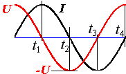
Described intervals t. 1 I. t. 2 will be half the period of complete oscillation in the circuit.
In the second half, processes are similar, only the capacitor will be discharged from the negative value, and the current and the magnetic flow will change the direction. Magnetic energy will again accumulate in the coil during time t. 3, replacing the polarity of poles.
For the final stage of oscillations ( t. 4), the accumulated magnetic energy of the coil charges the capacitor to the initial value U. (In the absence of losses) and the oscillation process will repeat.
In reality, if there is energy losses on the active resistance of conductors, phase and magnetic losses, fluctuations will be attenuating amplitude.
Time t. 1 + t. 2 + t. 3 + t. 4 will be a period of oscillations ![]() .
.
Frequency of free oscillations circuit ƒ \u003d 1 / T.
![]()
The frequency of free oscillations is the frequency of the contour resonance, on which the inductance reactive resistance X L \u003d 2πFL Equal to the reactive capacity resistance X C \u003d 1 / (2πFC).
Calculation of frequency resonance LC- Konter:
A simple online calculator is proposed for calculating the resonant frequency of the oscillating circuit.
Problem Statement: We already know a lot about mechanical oscillations: free and forced oscillations, self-oscillates, resonance, etc. Start the study of electrical oscillations. The theme of today's lesson: obtaining free electromagnetic oscillations.
Recall the first: what conditions should the oscillatory system, a system in which free oscillations may occur. Answer: In the oscillatory system, the returning force should occur and the conversion of energy from one species to another.
(Collapse a new material on a presentation with a detailed explanation of all processes and records in the notebook of the first two-quarters of the period, 3 and 4 quarters to describe the house, according to the sample).
The oscillating circuit is an electrical chain in which free electromagnetic oscillations can be obtained. Kk It consists of all of the two devices: coils with inductance L and capacitor with electricity C. The perfect oscillating circuit has no resistance.
To inform energy in KK, i.e. To withdraw it from the equilibrium position, it is necessary to temporarily open its chain and put the key with two positions. When the key is closed on the current source, the condenser charges to the maximum charge. This is served in K.K. Energy in the form of electric field energy. When the key is closed into the right position, the current source is disabled, kk.k. Granted to itself.

Such condition kk Corresponds to the position of the mathematical pendulum in the extreme right position when it was removed from the state of rest. The oscillating circuit was derived from the equilibrium position of the capacitor - maximum and the energy of the charged condenser - the energy of the electric field is maximum. We will consider the whole process that occurs in it on the quarters of the period.

At the 1st point, the capacitor is charged to a maximum charge (the lower title is charged positively), the energy in it is concentrated in the form of an electric field. The condenser is closed by himself, and it begins to discharge. Positive charges by the law of the coulon are attracted to the negative, and the discharge current arises counterclockwise. If there were no inductance coils on the path, then everything would have happened instantly: the capacitor would simply discharge. The accumulated charges would compensate each other, the electric power would turn into thermal. But in the coil there is a magnetic field, the direction of which can be determined by the rule of the bull - "up". The magnetic field is growing and occurs the phenomenon of self-induction, which prevents the current growth in it. The current is growing not instantly, but gradually, throughout the 1st quarter of the period. During this time, the current will grow until the condenser supports it. As soon as the capacitor will discharge, the current is no longer growing, he will reach this point maximum value. The capacitor was discharged, the charge is 0, which means the energy of the electric field is 0. But the maximum current flows in the coil, there is a magnetic field around the coil, which means that the electric field energy turns into the magnetic field energy. By the end of the 1st quarter of the period in K.K.T. Maximum, the energy is concentrated in the coil in the form of the magnetic field energy. This corresponds to the position of the pendulum when it passes the position of the equilibrium.

At the beginning of the 2nd quarter of the period, the condenser is discharged, and the current reached the maximum value and it would have to instantly disappear, because the capacitor does not support it. And the current really begins to decrease sharply, but it flows through the coil, and there is a phenomenon of self-induction, which prevents any change in the magnetic field causing this phenomenon. EMF self-induction supports an endungent magnetic field, the induction current has the same direction as the existing one. In kk Current flows counterclockwise - in an empty capacitor. The condenser accumulates electric charge - on top-end - positive charge. The current flows until it supports the magnetic field, until the end of the 2nd quarter of the period. The capacitor charges to the maximum charge (if energy does not occur), but the opposite direction. They say the condenser recharged. By the end of the 2nd quarter of the current period disappears, it means that the magnetic field energy is equal to 0. Interpretation reloaded, its charge is equal to (- maximum). Energy is concentrated in the form of an electric field. During this quarter, there was a transformation of the magnetic field energy into the energy of the electric field. The state of the oscillating circuit corresponds to this position of the pendulum, in which it deflects to the leftmost position.

In the 3rd quarter of the period, everything is also happening as in the 1st quarter, only the opposite direction. The capacitor begins to discharge. The discharge current is growing gradually, throughout the quarter, because The rapid growth is hampered by the phenomenon of self-induction. The current is growing to the maximum value until the capacitor is discharged. By the end of the 3rd quarter, the energy of the electric field will turn into the magnetic field energy, completely, if there is no leakage. This corresponds to this position of the pendulum when it passes the position of the equilibrium, but in the opposite direction.

In the 4th quarter of the period, everything happens the same as in the 2nd quarter, only in the opposite direction. The current supported by the magnetic field is gradually decreasing, supported by self-induction EMF and recharges the condenser, i.e. Returns it to the initial position. The magnetic field energy turns into an electric field energy. What corresponds to the return of the mathematical pendulum in the original position.
Analysis of the considered material:
1. Is the oscillatory contour to consider how the oscillatory system? Answer: 1. In the oscillatory circuit, the energy of the electric field is converted into the energy of the magnetic field and vice versa. 2. The phenomenon of self-induction plays the role of returns. Therefore, the oscillatory contour is considered as an oscillatory system. 3. oscillations in K.K. can be considered free.
2. Can be fluctuations in kk. Consider how harmonic? We analyze the change in the size and sign of the charge on the condenser plates and the instantaneous value of the current and its directions in the chain.

The graph shows:
3. What fluctuate the circuit fluctuates? What physical bodies do oscillatory movements? Answer: electrons fluctuate, they make free oscillations.
4. What physical quantities change when the oscillating circuit is performed? Answer: Current power changes in the chain charge, the capacitor charge, the voltage on the condenser plates, the energy of the electric field and the magnetic field energy.
5. The period of oscillations in the oscillatory circuit depends only on the inductance of the coil L and the capacitance of the condenser C. Thomson formula: T \u003d 2π can be compared with formulas for mechanical oscillations.
Electric oscillating circuit is a system for excitation and maintaining electromagnetic oscillations. In the simplest form, this is a chain consisting of a sequentially connected coil with the inductance L, capacitor with a container with and resistor resistance R (Fig. 129). When the switch P is mounted in position 1, the capacitor C is charged to voltage. U. t. . At the same time, an electrical field is formed between the capacitor plates, the maximum energy of which is equal to
When transferring the switch to position 2, the contour closes and the following processes proceed in it. The capacitor begins to discharge and the circuit will go to the current i.,
whose value increases from zero to the maximum value  And then again decreases to zero. Since a variable current flows in the chain, an EDC is induced in the coil, which prevents the discharge of the capacitor. Therefore, the process of dischargeing the condenser does not occur instantly, but gradually. As a result of the current in the coil, a magnetic field occurs, the energy of which
  reaches the maximum value at a current equal
  . The maximum magnetic field energy will be equal to

After reaching the maximum value, the current in the circuit will begin to decrease. In this case, the capacitor will occur, the magnetic field energy in the coil will decrease, and the energy of the electric field in the condenser increase. Upon reaching the maximum value. The process will begin to repeat and fluctuations in electrical and magnetic fields occur in the circuit. If we assume that resistance  (i.e., the energy for heating is not spent), then according to the law of energy conservation, the total energy W. Standing remains

and  ;
; .
.
The contour in which the energy loss does not occur is ideal. Voltage and current in the circuit vary by harmonic law
 ;
;

where  - Circular (cyclic) oscillation frequency
  .
.
Circular frequency is associated with frequency of oscillations  and periods of oscillations T ratio.
N.  and fig. 130 presents graphs of voltage change and current I in the coil of the perfect oscillatory circuit. It can be seen that the power of the current is lagging behind the voltage phase
  .
.
 ;
;
 ;
; - Thomson formula.
In the event that resistance  , Thomson formula takes the view
 .
.
Basics of Maxwell theory
The theory of Maxwell is called the theory of a single electromagnetic field created by an arbitrary system of charges and currents. The theory solves the main task of electrodynamics - according to a given distribution of charges and currents, the characteristics of the electrical and magnetic fields created by them are selected. Maxwell's theory is a generalization of the most important laws describing electrical and electromagnetic phenomena - the Ostrogradsky-Gauss theorems for electrical and magnetic fields, the law of the total current, the law of electromagnetic induction and the theorem on the circulation of the electric field strength vector. Maxwell Theory is phenomenological, i.e. It does not consider the internal mechanism of phenomena occurring in the medium and causing the appearance of electrical and magnetic fields. In the theory of Maxwell, the medium is described by three characteristics - dielectric ε and magnetic μ permeability of the medium and the electrical conductivity γ.


