IN different models Color-music installations are used various methods Conjugation with signal source. Some of them are connected without wires of wires, others require the use of soldering.
Instruction
To collect a colorwoman on LEDs with your own hands, you need to have basic knowledge of electronics, be able to read the schemes and work with a soldering iron. In the article, we will look at how the colorwoman on the LEDs, the main working circuits, on the basis of which you can collect on your own ready-made devices, and at the end step by step we will collect the finished device using the example.
What kind of principle is a colorwoman
At the heart of the color-music installations, the method of frequency conversion of music and its transfer is used, by means of individual channels, to control light sources. As a result, it turns out that, depending on the main musical parameters, the work of the color system will match it. On this trailer, a scheme is based on the colorwoman on the LEDs with their own hands.
As a rule, no less than three different colors are used to create color effects. It may be blue, green and red. Mixing in various combinations, with a different duration, they are able to create an amazing atmosphere of fun.
Separate a signal to low, medium and high purity, capable LC and RC filters, which are installed and configured into the color-duty system with the use of LEDs.
Filter settings are set to the following parameters:
- up to 300 Hz on a low-frequency filter, as a rule, its color is red;
- 250-2500 Hz for medium, green color;
- all that above 2000 Hz converts a high-frequency filter, as a rule, the operation of the blue LED depends on it.
Frequency division is carried out with a small overlap, it is necessary, to obtain various color shades, when the instrument is operating.
Color selection, in this color music scheme is not fundamental, and if you wish, you can use the LEDs of different colors at your discretion, to change places and experiment, no one can prohibit. Various frequency fluctuations in combination with the use of non-standard color solutions can significantly affect the quality of the result.
Scheme parameters such as the number of channels and their frequency are available for adjustment, from which it can be concluded that the colorwoman can use a large number of LEDs of different colors, and it is possible to individual adjustment of each of them in terms of frequency and width of the channel.
What is necessary, for the manufacture of color music
The resistors for the color-music installation, our own production, can only be used permanent, with a power of 0.25-0.125. Suitable resistors can be seen in the figure below. Strips on the housing show the resistance value.

Also, R3 resistors are used in the diagram, and the rapid r - 10, 14, 7 and R 18, regardless of the type. The main requirement is the ability to install on a fee used when assembling. The first version of the LED color music, was collected using the resistor aC type With the designation of SPZ-4BM and imported - trickening.

As for the capacitors, it is necessary to use the parts with a 16 volt operating voltage, not less. Type maybe any. With difficulty in finding a C7 condenser, you can connect parallel, two smaller in terms of capacity, to obtain the required parameters.
The C1, C6 capacitors used in the LED colorwriter scheme must be able to work for 10 volts, respectively, C9-16V, C8-25V. If instead of old Soviet capacitors, it is planned to use new, imported that it is worth remembering that they have a difference in the designation, it is necessary to determine the polarity of the capacitors in advance, which will be installed, otherwise you can confuse and spoil the scheme.

Even for the manufacture of colorwomen, a diode bridge will be required, with a voltage of 50V and a working current, about 200 million. In the event that there is no possibility to install the finished diode bridge, you can make it from several rectifiable diodesFor convenience, they can be removed from the board and mounted separately using a smaller board.

The parameters of diodes are selected similarly used in the factory execution of the bridge, diodes.
LEDs should be red, blue and angry glow. For one channel, they will need six pieces.
Another necessary element, voltage stabilizer. A plaintious stabilizer, imported production, with article 7805 is used. 7809 (ninety) can also be used, but then the R22 resistor must be excluded from the circuit, and the jumper connects the minus tire and the average output instead.
Connect the color music S. music Center, It is possible with the help of a three-pin "Jack" connector.

And the last thing you need to have for the assembly is a transformer with suitable voltage parameters.
General scheme for assembling the colorwoman, in which the described parts are used in the photo below.

Multiple working circuits
Below will be offered several working circuits of the colorwoman on LEDs.
Option number 1
For this scheme, you can use any type LEDs. The main thing is that they are supermarket and different on the luminescence. The scheme works on the following principle, the signal from the source is transmitted to the input, where the channel signals are summed up and then sent to the variable resistance. (R6, R7, R8) using this resistance the signal level for each channel is adjustable, after which the filters arrive. The difference in filters, in the capacitance of the capacitors used for their assembly. Their meaning, as in other devices, convert and clean the sound range in certain boundaries. This is the top, medium and low frequencies. For adjustment in the color music diagram, adjustment resistors are installed. Having passed all this, the signal enters the microcircuit that allows you to install various LEDs.

Option number 2.
The second version of the colorwoman on the LEDs is characterized by its simplicity and suitable for beginner lovers. The scheme involves the amplifier and three channels for frequency processing. A transformer is installed, without which you can do it if the signal at the input is sufficient to open the LEDs. As in similar schemes, adjustment resistors are applied, designated as R4 - 6. Transistors can be used any, most importantly, to transfer more than 50% current. In fact, nothing more is required. The scheme, if desired, can be improved, to obtain a more powerful color-chicted installation.

Step-by-step assembly of the simplest color music model
For the assembly of simple colorwomen on LEDs, the following materials will be required:
- lEDs in size are five millimeters;
- wire from old headphones;
- original or analog of transistor KT817;
- 12 volt power supply;
- several wires;
- a piece of plexiglass;
- adhesive pistol.
The first where to start, make it, the body of future colorwomen from the plexiglass. For this it is cut in size and glued, glue gun. The box is better to make a rectangular shape. Dimensions can be adjusted for themselves.

To calculate the number of LEDs, we divide the voltage of the adapter (12B), on the working LEDs (3B). It turns out we need to install 4 LEDs.
Cable from headphones we clean, in it three wires, we will use one left or right channel, and one in common.

One wire we will not need and can be isolate it.
The simple color music scheme on the LEDs is as follows:

Before assembly, cable making inside the box.
lEDs have polarity, respectively, when connected, it must be taken into account.
In the process of assembly, you need to try not to heat the transistor, since it can lead to its breakdown, and take into account the labeling on the legs. Emitter is indicated as (e), base and collector, respectively (b) and (k). After assembly and check, you can install the top cover.

Ready version of the colorwoman on LEDs
In conclusion, I would like to say that it is not so difficult to collect a colorwoman on the LEDs as it may seem at first. Of course, if you need a device with beautiful design, then here you will have to spend a lot of time and effort. But for the manufacture of simple colorwomen in familiarization or entertainment purposes, it is enough to collect one of the schemes presented in the article.
Small color music
The colorwoman homemade in the cabin of its own car will be interesting to all lovers of beautiful disco music. Make it with your own hands is completely easy.
The colorwoman at home can be quickly and easily assembled, if you know some nuances of the circuit and its correct installation.
Schemes of colorwoman in auto
A large number of schemes of self-made colorwoman published on the forums of radio amateurs. Some of those are intended only for experienced, others - for beginner craftsmen.
In principle, all schemes are built according to one principle, which is recommended to understand that the assembly does not represent more something impracticable and very complex.
Simple scheme
Even a schoolboy is able to collect on such a scheme, because it consists of only one transistor. The name of its CT815g.
This colorwoman can be collected on diodes borrowed from a simple pocket flashlight.
It is done as follows:
- LEDs that we removed from a pocket flashlight, we divide in half;
- We find a suitable box in which we will collect our scheme. Ideal in B. this case Instead of a box, a rectangular plastic box from the used shoe cream;
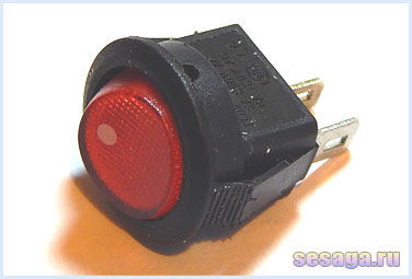
- Switch we endure. It will change the mode of light music on simple lighting.
Note. LEDs will flash under the bass and the greater the volume, the brighter they light. As for the channels, there are enough two not connected to the dynamics.
- The source of power in our case will be three finger batteries;
- It remains only to put a self-made colorwoman in the trunk and enjoy the effect.
Sophisticated schemes
They will create more professional from the point of view of the user, schemes.
The first version of the scheme
She is going on five diodes. All of them are five millionth and 3 V, have transparent lenses. KT815 or CT972 is taken as the transistor. Its task is to strengthen and execute the role of the key.
Everything is done like this:
- Served meals from 2 half-rolled batteries;
- Music inputs, respectively, two: x1 and x2;
- I set the red diode in place LED3, the rest of the remaining pairs will be blue and green;
Note. As a result, we get very successful color-music scheme. The LEDs are very effectively glowing in the tact of music, the scheme consumes little current, and low frequencies are reproduced simply super. Only you need to be alert: from hands-free LEDs may not withstand and overdo it.
Second schema option
We find the transistor Kt817, wires, plug from headphones and diabetes.
Started:
- Transistor soldered according to the following scheme;
- Then the ribbon is added and everything moves into the luggage compartment of the car.
Light music from garland
A completely successful solution that will require the use of light bulbs from New Year's garlands:
- Garlands (see) must be collected together several pieces and secure the tape;
- Make an adapter for connecting to the head device and connect the wire.
Note. The scheme in this case will imply eight conductor twisted pairs that transmit a signal from the PI contacts to the colorwoman control unit.
Flowerwoman from LEDs
Original scheme for making beautiful color music. In this case, a hull is needed, which is made from the plexiglass.
Let's proceed:
- We select two plates with dimensions of 5x15 cm and two square plates 5x5 cm;
- In one of the details there is a pair of holes (for nutrition and headphones);
- We matize and whirl all the plates;
- We find LEDs that are also matting for a better effect;
- Corps we collect with the help of a thermal system, which is ideal for work with plexiglass;
- We collect now electrical circuit For colorwomen according to this scheme:
- We connect the wire from headphones with the appropriate connector to the car engine and enjoy the effect.
The body from the plexiglass can be installed in the cabin car, anywhere. Everything will depend on individual preferences, wire lengths, etc.
In the process of work, you must necessarily consider the following:
- The output voltage of the adapter and the rated voltage of each of the diodes should be interconnected. In other words, the total number of diodes involved in the scheme should be equal to the ratio of the output voltage of the adapter.
Note. As an example, if the adapter is 12V, and the voltage for each diode is given in 3B, then the total number of LEDs should be 4th.
- It is desirable to use the 3-wire wire, one of which should be left unused.
Scheme with a signal from the speaker
Another popular colorwoman creation scheme.
We do the following:
- Take a signal from speakers (see).
Note. It is very important not to close the output of the Uzp *. To this end, we connect only one wire.
UZP * - sound boards amplifier
- Suits the switch so that it turns on the LEDs on the music;
- We select resistance according to the scheme below, where the nominal value is specified to include one diode;
Note. If the colorwoman is assembled from 4 LEDs, the value of R must be 820 ohms.
Popular multicolored scheme
Another common scheme implies the possibility of increasing nutrition. This will especially be relevant if a chain is used from a plurality of LEDs.
Scheme such:
- Frequency filters should be two. They are in the entrance to pass HF and LF;
- The signal then enhances the amplifying cascades, after which the LEDs;
- It is recommended to connect the inputs 1 and 2 to the source dynamics.
Council. If there is a desire to make the colorwoman brighter, then you need to reduce the ratings of resistors to the pair of hundreds, and transistors change to KT817.
This scheme has one advantage that does not have any other: the ability to use LEDs of any color.
Thus, the red LED will flash when playing Babes, when playing SC and HF - green. As for the brightness setting, it is adjusted by the rotational volume of the sound: the higher the sound, the brighter the glow.
Ceiling car in LEDs
If there is a desire, you can not only arrange a similar disco in the car, but to build a backlight that or turned on separately or has been associated with musical reproduction. This operation Also implies the use of LEDs.
"Star Sky" on the car ceiling will look wonderful. This type of lighting, it turns out to be practiced for a long time and not only in cars, but also in its own apartments.
You can use this scheme in different ways:
- Post LEDs are uniformly, in arbitrary form or like a certain figure;
- Use different light bulb glow, imitating glow of asterisks (bright / not bright);
- Use different background Ceiling. For example, you can drag it into black.
Instructions for the creation:
- Thinking the car ceiling;
- We collect or acquire a current stabilizer.
Note. It is very important at this stage to do everything right. Otherwise, you will have to dismantle the collected ceiling if the diodes are blown. To avoid this situation, it is necessary after the assembly to control the scheme (find out how much volts and what power of the current in this scheme). The old BP from the computer is suitable as a test block.
- We use a large capacitor capacitor to make smooth quenching LEDs. Suitable, for example, KT470;
- Let's place the scheme in the matchbox;
- Checking the work, connecting three LEDs and one resistor;
- On the ceiling into the holes insert LEDs that are fixed on the reverse side by glue;
- Breeping also switch and stabilizer.
Note. LEDs can be grouped by 3 and connect to the resistor, and then the groups are carried out to the stabilizer in parallel.
That's all things. We hope that the reader will be able to choose something from the shown schemas. It is only necessary to not forget to take care of not to include a beautiful colorwoman while moving the car. It is very distracting from the road and can provoke an accident.
In the process of work, the video overview, photos - materials, schemes, and so on will be useful. Instructions like the above can be found in other articles of our site. The price of independent creation and installation of the colorwoman is considered the lowest autotuning in the world, because consumables can also be made with their own hands.
The inexhaustible potential of LEDs once again revealed in the design of new and modernization of the existing color-music consoles. 30 years ago, a colorwoman was considered a peak of fashion, collected from multi-colored light bulbs by 220 volts connected to a cassette tape recorder. Now the situation has changed and the tape recorder function now performs any multimedia device, and instead of incandescent lamps, ultra-light LEDs or LED tapes are installed.
The advantages of the LEDs in front of the light bulbs in the color-duty consoles are indisputable:
- wide color gamut and more rich light;
- various versions (discrete elements, modules, RGB ribbons, ruler);
- high response speed;
- low power consumption.
How to make a color music with a simple electronic circuit And make the LED flash from the sound frequency source? What are the transformation options sound signal exist? These and other issues will consider specific examples.
The simplest scheme with one LED
To begin with, it should be understood with a simple colorwoman circuit collected on one bipolar transistor, a resistor and the LED. Power on it can be served from a DC source with voltage from 6 to 12 volts. This colorwoman works on one transistor on the principle amplifying cascade With a common emitter. The perturbing effect in the form of a signal with a changing frequency and the amplitude enters the database VT1. As soon as the amplitude of oscillations exceeds some threshold, the transistor opens and the LED flashes.
The disadvantage of this simple scheme is that the pace of flashing the LED is completely dependent on the sound signal level. In other words, a full color-colored effect will be observed only at one volume level. Reducing the volume will lead to rare winking, and an increase - to almost constant luminescence.
Scheme with monochrome LED ribbon
The simplest color music on the transistor can be assembled using LED tape in the load. To do this, it is necessary to increase the supply voltage to 12V, select the transistor with the highest current current current in excess of the load current and recalculate the resistor's denomination. Such a simple color music from the LED tape is perfect for novice radio amateurs for assembling with their own hands even at home.
Simple three-channel scheme
Get rid of the shortcomings of the previous scheme allows a three-channel sound converter. The simplest colorwoman circuit with the separation of the audio range into three parts is shown in the figure.  It feeds on a constant voltage of 9V and can light one or two LEDs in each channel. The scheme of three independent amplifying cascades collected on KT315 transistors (CT3102), in which the different color LEDs are included. As an element for pre-amplification, you can use a small low-type network transformer.
The input signal is supplied to the secondary winding of the transformer, which performs two functions: galvanically unlock two devices and enhances the sound from linear output. Next, the signal enters three parallel filters collected on the basis of RC chains. Each of them works in a certain frequency band, which depends on the ratings of resistors and capacitors. The low-frequency filter passes sound fluctuations with a frequency of up to 300 Hz, as evidenced by the flashing of the Red LED. A sound in the range of 300-6000 Hz is passed through the average frequency filter, which is manifested in the flicker of the blue LED. The high-frequency filter passes a signal whose frequency is greater than 6000 Hz, which corresponds to the green LED. Each filter is equipped with a trimming resistor. With their help, you can specify a uniform glow of all LEDs, regardless of the musical genre. At the output of the circuit, all three filtered signals are enhanced by transistors.
If the power supply of the circuit is carried out from the low-voltage DC source, the transformer can be safely replaced by a single-circuit transistor amplifier.  First, the galvanic junction loses its practical meaning. Secondly, the transformer loses several times the diagram shown in the figure, by weight, size and cost. The scheme of a simple sound frequency amplifier consists of a CT3102 transistor, two capacitors that cut the constant component, and resistors providing the transistor with a common emitter mode. Using a trim resistor, you can achieve a general gain of a weak input signal.
In the case when it is necessary to increase the signal from the microphone, the electrical microphone is connected to the input of the previous scheme, feeding the potential from the power supply. A diagram of a two-stage pre-amplifier is shown in the figure.  In this case, the trimming resistor stands at the output of the first amplifying cascade, which gives more opportunities to adjust the sensitivity. Condensors C1-C3 skip the useful component and cut off the constant current. For implementation, any electret microphone will suit, for the normal operation of which enough displacement is 1.5V.
Colorwoman with RGB LED Ribbon
The following color-seated console scheme operates from 12 volts and can be installed in the car. It combined the basic functions of the previously considered schematic solutions and is capable of working in color music and lamp mode.
The first mode is achieved at the expense of the contactless RGB-ribbon control using a microphone, and the second - due to the simultaneous glow of the red, green and blue LEDs on full power. The selection of the mode is carried out using a switch placed on the board. Now let's stop in detail on how to make a colorwoman, which is perfectly suitable even for installation in a car, and which details will be required for this.
Structural scheme
To understand how this color-chicted console works, first consider its structural scheme. It will help trace the full way to pass the signal.  The source of the electrical signal is a microphone that converts sound oscillations from the phonogram. Because This signal is overly small, it must be enhanced using a transistor or operational amplifier. Then the automatic level controller (ARU) follows, which holds the oscillations of the sound within reasonable limits and prepares it to further process. Filters divide the signal to three components, each of which only works in one frequency range. In the end, it remains only to enhance the prepared current signal, which use transistors operating in key mode.
Schematic scheme
Based on structural blocks, you can proceed to consideration concept. Its general view is shown in the figure.  To limit the current consumption and stabilization of the supply voltage, the R12 resistor and the C9 condenser are installed. To set the microphone offset voltage, R1, R2, C1 is installed. Condenser C FC is selected individually to specific model Microphone in the process of adjustment. It is necessary in order to slightly muffle the signal of the frequency that prevails in the operation of the microphone. Usually reduce the effect of the high-frequency component.
Unstable voltage of the automotive network can affect the work of the colorwoman. Therefore, the most correctly connected homemade electronic devices through a 12V stabilizer.
Sound oscillations in the microphone are converted to an electrical signal and across C2 come to direct input of the operational amplifier DA1.1. From its output, the signal should be on the operation of the operational amplifier DA1.2, equipped with a chain feedback. Resistance resistance R5, R6 and R10, R11 Set the gain of DA1.1, DA1.2 equal to 11. OS circuit elements: VD1, VD2, C4, C5, R8, R9 and VT1, together with DA1.2, are part of the ARU. At the time of occurrence of the DA1.2 output of the signal too large amplitude, the VT1 transistor opens and via C4 closes the input signal to the general wire. This leads to an instantaneous reduction in outlet voltage.
Then stabilized alternating current Sound frequency passes through the cutting capacitor C8, after which it is divided into three RC filters: R13, C10 (LF), R14, C11, C12 (SC), R15, C13 (HF). In order for the colorwoman on the LEDs of the shine, it is clear enough to enhance the output current to the appropriate value. For a tape with consumption up to 0,5A, the transistors of the CT817 type transistors or imported BD139 without installation on the radiator are suitable. If the collected light summission does with their own hands implies the load of about 1a, then the transistors will need forced cooling.
In the collectors of each output transistor (parallel to output) there are D6-D8 diodes, whose cathode are combined with each other and are displayed on the SA1 switch (WHITE LIGHT). The second switch of the switch is connected to the shared wire (GND). While SA1 is open, the scheme works in color music mode. When the switch contacts is closed, all the LEDs in the tape are ignited on the full brightness, forming a white stream of light in the amount.
PCB and assembly details
For the manufacture of pCB It will take a one-sided textolitol size 50 to 90 mm and a ready-made file.lay that can be downloaded. For clarity, the board is shown by radio elements. Before printing, you must specify its mirror image. The M1 layer shows 3 jumpers placed on the part side.  For the assembly of the colorwoman from the LED tape, you will need accessible and inexpensive components. An electret type microphone is suitable in a protective housing with old audio equipment. The light music is collected on the TL072 chip in the DIP8 case. Capacitors, regardless of type, should have a supply of voltage and be designed for 16V or 25V. If necessary, the design of the board allows you to set output transistors into small radiators. From the edge, the terminal block is placed on 6 positions for power supply, connecting RGB LED tape and switch. The full list of items is given in the table.
  In conclusion, I would like to note that the number of output channels in a homemade color-duty console can be increased by how much it pleases. To do this, you need to split the entire frequency range on large quantity Sectors and recalculate the bandwidth of each RC filter. To the outputs of additional amplifiers, connect intermediate colors LEDs: purple, turquoise, orange. From such an improvement of the colorwoman with their own hands will be only more beautiful.
The following schemes belong to the CXEm.net site
Read the same way
Articles We met with the principle of work of the color-music console, considered the fundamental scheme and disassembled all the radiocompunists, of which the prefix will be.
Continue collect a color-duty prefix on LEDs And let's start with the printed circuit board.
The appearance of the printed fee of the prefixes from the tracks is shown in the figure below.

The printed circuit board is made of one-sided foil fiberglass thickness 0.5 mm thick. The red lines show the connection of tricks of trimming resistors on the board. The lines with arrows indicate the connection to external elements Schemes: LEDs HL1 - HL24, to the X1 connector, to the variable resistor R3 and the secondary winding of the T1 transformer.
The appearance of the finished fee from the part side, as well as their location and numbering according to the schematic diagram are shown in the following figure.

The flow-screen console fee is located in the lower part of the plastic casing case, and its dimensions are 45 x 80 mm. How the printed circuit board is described in detail and shown.

In addition to this, I apply a working drawing of a circuit board with detail, made on a notebook sheet.

The LEDs of the channels are located on a separate board with dimensions of 45 x 45 mm and combined into groups. Each group consists of three LEDs connected in series, forming a lamp of one color.

In each channel of the console, 6 LEDs are used, from which two lamps are obtained on the channel.

Figure PCB with LEDs is shown below. For the convenience of understanding the location lED lamps On the board, each lamp is highlighted by its color.


5. The body of the color-chicted console.
As a body for the console in the author, a small ceiling is used, designed to illuminate the rooms and consisting of plastic base and a glass bowl screwing into a plastic base. Such a plane can be purchased at any store of electrical engineering or in MEGAST-type stores, etc.
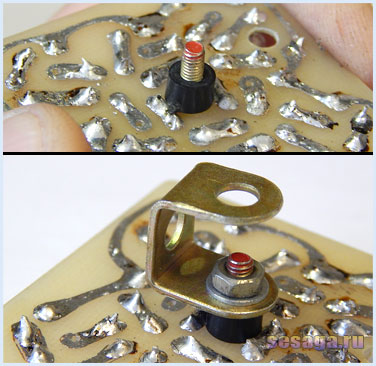
A cartridge is removed from the ceiling and a transformer is installed on its place, over which fee with LEDs.
![]()
The transformer is attached in the middle of the plastic base using a clamp that can be done, for example, from a strip of aluminum with a thickness of 1 mm. If the transformer has its own fastening elements, the transformer is attached with them.
To install the board with LEDs, a small M-shaped rack is made, the vertical size of which is selected in such a way that the board is at the level of the middle of the ceiling. The rack can be made of elements of a children's designer or from a strip of aluminum.

To the rack, the board with LEDs is screwed by a screw through the plastic sleeve to isolate the tracks from the metal contact and be able to rotate the board around its axis.


The circuit board with details is located in the lower part of the plastic case and is attached to the jumper to which the cartridge was fixed. For mounting board, a regular hole in the jumper and screw is used.


At the base of the case along the edges of the transformer, four holes are necessary, through which the segments of the mounting wire will be passed from the main board to the outputs of the secondary winding of the transformer and the board with LEDs.

If when screwed into the housing, the glass ball will sit under a small angle, then the head of the screw fastening the M-shaped rack is blamed. To remove this breakdown, it is necessary to spin the same screw from the opposite side.


If you wish, you can install the power switch on the side wall of the plastic base.

The feeding and signaling wire is rented into the housing on the sides of the switch, and the node is tied inside on each, so that the wires can not be caught out. Signal wire can be taken from a faulty computer mouse.


A computer column with a linear output will be used as a sound signal source and a jack type connector for three contacts will be used to connect to the console. If you use another sound source, which has a different type of connection, such as tulips, then solder tulips.

6. Setting.
Immediately after turning on the color-music console, check the voltage at the condenser condenser with C9 - it should be within 9 - 10V. If the luminosity of the LEDs of one of the channels is observed, the movement of the LED will be achieved by the engine of the trim resistor of the corresponding channel. How to measure the voltage to the multimeter read in the article.
Setting the consoles are produced when playing a musical composition.
The R3 variable resistor engine is translated into the average position, and the engines of the R7, R10, R14, R18, R10, R14, R18 moves so that the LEDs flashed into tact with music. If the brightness of the LED will be insufficient, reduce the resistance of current-limiting resistors included in the circuit with LEDs.
In order to more accurately select the work of each channel, the prefix is \u200b\u200bdesirable to configure using several different compositions.
The constructive design of the color-music console is made in such a way that it can be attached to the wall or use as a desktop version. If the prefix is \u200b\u200bused in the form of a desktop version, the board with LEDs must be tilted at an angle of 60 - 70 °. It is experimentally established that with such a slope of the rays of the LEDs are projected on the border of the transition of the side and top of the ceiling, forms the maximum number of color shades.


With a small refinement of the scheme, the color-music console can be collected on miniature incandescent lamps. For this, the LEDs are removed from the circuit, current-limiting resistors that are consistent with the LEDs are removed, the power transformer is replaced to a more powerful, and the roll stabilizer5 is installed on the radiator, since it will take a larger current. Everything else remains unchanged. One channel can be connected from 3 to 5 lamps connected in parallel.
As a supplement to the article, see the second part of the video, where the splitting of the LEDs on the fee is shown, the final assembly and the work of the color-music console. As always, in the course of the roller are given useful advice and recommendations.
If questions arose on production of colorwoman on LEDs Or lamps - Write in the comments to the article.
Good luck!
Literature:
1. I. Andrianov "Consoles to radio receivers".
2. Radio 1990 №8, B. Sergeev "Simple color-music consoles".
3. Operation on the "Start" radio constructor.


