/ Protocols / Connection
TCP / IP protocol family
The name TCP / IP comes from the two main protocols in this family - TCP (Transmission Control Protocol) and IP (Internet Protocol). They are responsible for the reliable transfer of data between computers. IP is closely related to the concept of an IP address - the unique address of a computer on a network.
TCP - transport protocol
According to this protocol, any message is cut into packets (IP packets) of approximately the same size and format, these packets are numbered and transmitted independently of each other, and the original message is assembled from the received packets at the destination. In case of loss of one packet, you can send a request for its retransmission (or ask to repeat all packets). In some cases, retransmission does not make sense, for example, when transmitting sound and images in real time.
IP protocol - routing protocol
According to this protocol, each packet, except for the data embedded in it, has a header that is only 20 bytes long. It contains the sender's computer address (IP address) and the recipient's address, and other information needed to properly assemble packets at the destination.
In local networks, the path along which the packet is transmitted is determined by the geometric structure of the network and possible ways connections of nodes. Knowing this, you can specify the exact path that data passes when transmitting a message from one computer on the local network to another.
In wide area networks and the Internet, the route of each packet is dynamically determined during transmission. This guarantees optimal loading of the components and the resistance of the system to damage to individual sections. Special devices - routers - choose the path of the packet and send it to the next node on the network. The principle of dynamic routing is called flexible routing.
For the first time, the principles of packet switching and flexible routing were applied in the United States during the development of the ARPANET in 1969. This is why ARPANET is considered the prototype of the Internet TCP / IP - the foundation of the Internet
The user most often deals with application protocols. Each application protocol has its own service or Internet service.
For example, HTTP protocol deals with WWW documents - Web pages, users work over the HTTP protocol.
FTP protocol allows you to transfer information over the network in the form of files.
Postage POP and SMTP protocols provide connection to mail servers, sending and delivery of letters.
NNTP protocol allows you to work with the news service.
Data transfer protocol TCP / IP
The Internet, which is a network of networks and unites a huge number of different local, regional and corporate networks, functions and develops thanks to the use of a single data transfer protocol TCP / IP. The term TCP / IP includes the names of two protocols:
- Transmission Control Protocol (TCP) - transport protocol;
- Internet Protocol (IP) is a routing protocol.
Routing protocol. The IP protocol allows information to be transferred between computers on a network. Consider a job of this protocol by analogy with the transmission of information using regular mail. In order for the letter to reach its destination, the address of the recipient (to whom the letter is sent) and the address of the sender (from whom the letter is sent) are indicated on the envelope.
Similarly, information transmitted over the network is "packed in an envelope" on which the IP addresses of the recipient and sender computers are written, for example, "To: 198.78.213.185", "From: 193.124.5.33". The contents of the envelope in computer language are called IP packet and is a collection of bytes.
In the process of forwarding ordinary letters, they are first delivered to the post office closest to the sender, and then transferred through a chain of post offices to the post office closest to the recipient. At intermediate post offices, letters are sorted, that is, it is determined to which next post office one or another letter should be sent.
IP packets on their way to the destination computer also pass through numerous intermediate Internet servers on which the operation is performed routing... As a result of routing, IP packets are directed from one Internet server to another, gradually approaching the receiving computer.
Internet Protocol (IP) provides routing of IP packets, that is, the delivery of information from the sending computer to the receiving computer.
Determination of the route of information passage. The "geography" of the Internet differs significantly from the geography we are used to. The speed of obtaining information does not depend on the remoteness of the Web server, but on the number of intermediate servers and the quality of communication lines (their bandwidth), through which information is transmitted from node to node.
It is quite easy to get acquainted with the route of information passage on the Internet. Special program tracert.exe, which is part of Windows, allows you to trace through which servers and with what delay information is transmitted from the selected Internet server to your computer.
Let's trace how the access to information in the "Moscow" part of the Internet to one of the most popular search servers is realized Russian Internet www.rambler.ru.
Determining the route of information passage
2. In the window MS-DOS session when prompted by the system to enter a command.
3. After a while, a trace of information transfer will appear, that is, a list of nodes through which information is transmitted to your computer, and the time of transfer between nodes.
 |
Tracing the information transmission route shows that the www.rambler.ru server is at a "distance" of 7 hops from us, that is, information is transmitted through six intermediate Internet servers (through the servers of the Moscow providers MTU-Inform and Demos). The speed of information transfer between nodes is quite high; one "hop" takes from 126 to 138 ms.
Transport protocol. Now let's imagine that we need to send a multi-page manuscript by mail, but the mail does not accept parcels or parcels. The idea is simple: if the manuscript does not fit in a regular mail envelope, it must be taken apart into sheets and sent in several envelopes. In this case, the sheets of the manuscript must be numbered so that the recipient knows in what sequence to connect these sheets later.
On the Internet, a similar situation often occurs when computers exchange large files. If you send such a file as a whole, then it can "clog" the communication channel for a long time, make it inaccessible for sending other messages.
To prevent this from happening, it is necessary to split a large file into small parts on the sending computer, number them and transport them in separate IP packets to the receiving computer. On the receiving computer, you must assemble the source file from the individual parts in the correct sequence.
Transmission Control Protocol (TCP), that is, the transport protocol, provides the splitting of files into IP packets in the process of transmission and the assembly of files in the process of receiving.
Interestingly, for the IP protocol, which is responsible for routing, these packets are completely unrelated to each other. Therefore, the last IP packet may well overtake the first IP packet along the way. It may happen that even the delivery routes of these packets will turn out to be completely different. However, TCP will wait for the first IP packet and reassemble the source file in the correct sequence.
Determination of the time of exchange of IP packets. The time of exchange of IP packets between local computer and the Internet server can be determined using the ping utility included with operating system Windows. The utility sends four IP packets to the specified address and shows the cumulative transmission and reception times for each packet.
Determining the time of exchange of IP packets
1. Connect to the Internet, enter the command [Programs-MS-DOS Session].
2. In the window MS-DOS session when prompted by the system to enter a command.
3. In the window MS-DOS session the result of the test signal passage in four attempts will be displayed. The response time characterizes the speed parameters of the entire chain of communication lines from the server to the local computer.
 |
Questions to Think About
1. What ensures the holistic functioning of the global computer network Internet?
Practical tasks
4.5. Trace the route of information passing from one of the most popular Internet search servers www.yahoo.com located in the "American" segment of the Internet.
4.6. Determine the time of exchange of IP packets with the www.yahoo.com server.
The Internet, which is a network of networks and unites a huge number of different local, regional and corporate networks, functions and develops thanks to the use of a single TCP / IP data transfer protocol. The term TCP / IP includes the names of two protocols:
Transmission Control Protocol (TCP) - transport protocol;
Internet Protocol (IP)- routing protocol.
Routing protocol. The IP protocol allows information to be transferred between computers on a network. Let's consider the operation of this protocol by analogy with the transfer of information using regular mail. In order for the letter to reach its destination, the address of the recipient (to whom the letter is sent) and the address of the sender (from whom the letter is sent) are indicated on the envelope.
Similarly, information transmitted over the network is "packed in an envelope" on which the IP addresses of the recipient and sender computers are "written", for example "To: 198.78.213.185", "From: 193.124.5.33". The contents of the envelope in computer language are called IP packet and is a collection of bytes.
In the process of forwarding ordinary letters, they are first delivered to the post office closest to the sender, and then transferred through a chain of post offices to the post office closest to the recipient. At intermediate post offices, letters are sorted, that is, it is determined to which next post office one or another letter should be sent.
IP packets on their way to the destination computer also pass through numerous intermediate Internet servers on which the operation is performed routing. As a result of routing, IP packets are directed from one Internet server to another, gradually approaching the receiving computer.
Determination of the route of information passage. The “geography” of the Internet differs significantly from the geography we are used to. The speed of obtaining information does not depend on the remoteness of the Web server, but on the number of intermediate servers and the quality of communication lines (their bandwidth) through which information is transmitted from node to node.
It is quite easy to get acquainted with the route of information passage on the Internet. Special program tracert.exe, which is part of Windows, allows you to trace through which servers and with what delay information is transmitted from the selected Internet server to your computer.
Transport protocol... Now let's imagine that we need to send a multi-page manuscript by mail, but the mail does not accept parcels or parcels. The idea is simple: if the manuscript does not fit in a regular mail envelope, it must be taken apart into sheets and sent in several envelopes. In this case, the sheets of the manuscript must be numbered so that the recipient knows in what sequence to connect these sheets later.
On the Internet, a similar situation often occurs when computers exchange large files. If you send such a file as a whole, then it can "clog" the communication channel for a long time, make it inaccessible for sending other messages.
To prevent this from happening, it is necessary to split a large file into small parts on the sending computer, number them and transport them in separate IP packets to the receiving computer. On the receiving computer, you must assemble the source file from the individual parts in the correct sequence.
Interestingly, for the IP protocol responsible for routing, these packets are completely unrelated to each other. Therefore, the last IP packet may well overtake the first IP packet along the way. It may happen that even the delivery routes of these packets will turn out to be completely different. However, TCP will wait for the first IP packet and reassemble the source file in the correct sequence.
Transmission Control Protocol (TCP), which is a transport protocol, provides for splitting files into IP packets during transmission and assembling files during receiving.
The time of exchange of IP packets between the local computer and the Internet server can be determined using the utility ping, which is part of the operating room Windows systems... "The utility sends four IP packets to the specified address and shows the total transmit and receive time for each packet.
A computer on a TCP / IP network can have addresses of three levels (but not less than two):
- The local address of the computer. For nodes included in local area networks Is the MAC address network adapter... These addresses are assigned by equipment manufacturers and are unique addresses.
- An IP address of 4 bytes, for example 109.26.17.100. This address is used at the network level. It is assigned by the administrator when configuring computers and routers.
- Symbolic identifier-name (DNS), such as www.site
Network protocols
A network protocol is a set of rules that allows data exchange between devices that make up a network, for example, between two network cards(fig. 1).
Rice. 1. Illustration for the concept of Network Protocol
A stack is a set of multi-level protocols grouped together.
The TCP / IP protocol stack is the two protocols that are the backbone of communication on the Internet. The TCP protocol breaks the transmitted information into portions (packets) and numbers them. Using IP, all packets are sent to the recipient. Next, using the TCP protocol, it is checked whether all packets are received. When all portions are received, TCP arranges them in the correct order and assembles them into a single whole. Two versions of this protocol are used on the Internet:
- IPv4 routable network protocol. In this version of the protocol, each node on the network is assigned a 32-bit IP address (i.e. 4 octets or 4 bytes).
- IPv6 allows you to address significantly large quantity nodes than IPv4. Internet Protocol version 6 uses 128-bit addresses, and can identify significantly more addresses.
V6 IP addresses are written as X: X: X: X: X: X: X: X, where X is hexadecimal number, consisting of 4 characters (16 bits), and each number has a size of 4 bits. Each number ranges from 0 to F. Here is an example of an IP address for version 6: 1080: 0: 0: 0: 7: 800: 300C: 427A. In such a record, insignificant zeros can be omitted, so the fragment of the address: 0800: is written as 800 :.
It is customary to write IP addresses by breaking the entire address into octets (8), each octet is written as a decimal number, the numbers are separated by dots. For example, the address
10100000010100010000010110000011
written as
10100000.01010001.00000101.10000011 = 160.81.5.131
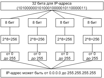
Rice. 2 Translation of an address from binary system decimal
A host IP address consists of an IP network number that occupies the upper portion of the address, and a host number on that network that occupies the lower portion.
160.81.5.131 - IP address
160.81.5. - network number
131 - host number
Basic protocols (IP, TCP, UDP)
TCP / IP is a collective name for a set (stack) network protocols different levels used on the Internet. Features of TCP / IP:
- Open protocol standards developed independently of software and hardware;
- Independence from the physical transmission medium;
- Unique addressing system;
- High-level standardized protocols for common custom services.
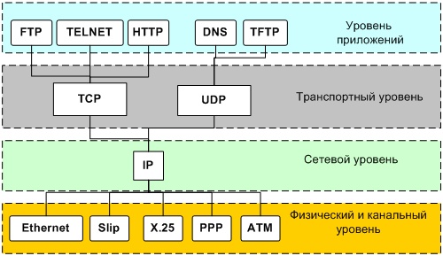
Rice. 3 TCP / IP protocol stack
The TCP / IP protocol stack is divided into 4 layers:
- Applied
- Transport
- Internetwork
- Physical and channel.
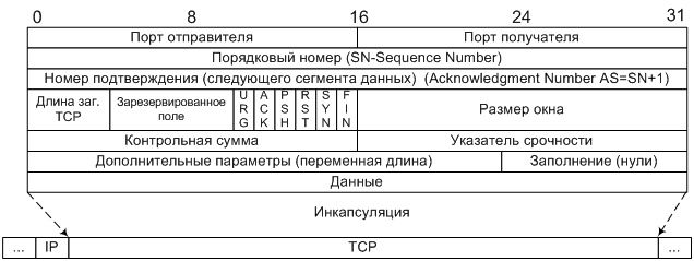
Data is transferred in packets. Packages have a header and ending that contain service information. Data from higher levels are inserted into packages of lower levels.

Rice. 4 Example of packet encapsulation in a TCP / IP stack
Physical and data link layer.
The TCP / IP stack does not imply the use of any specific media access layer protocols and physical media. From the layer of access to the transmission medium, an interface with the IP module is required to ensure the transmission of IP packets. You also need to ensure that the IP address of the host to which the IP packet is sent to a MAC address is required. Often, entire protocol stacks can act as a layer of access to the transmission medium, then they talk about IP over ATM, IP over IPX, IP over X.25, etc.
Internet layer and IP protocol.
This layer is based on the IP protocol.
IP (Internet Protocol) - Internet protocol.
The first IPv4 standard is defined in RFC-760 (DoD standard Internet Protocol J. Postel Jan-01-1980)
The latest version of IPv4 is RFC-791 (Internet Protocol J. Postel Sep-01-1981).
The first IPv6 standard is defined in RFC-1883 (Internet Protocol, Version 6 (IPv6) Specification S. Deering, R. Hinden December 1995)
The latest version of IPv6 is RFC-2460 (Internet Protocol, Version 6 (IPv6) Specification S. Deering, R. Hinden December 1998).
Main tasks:
- Addressing
- Routing
- Datagram fragmentation
- Data transfer
The IP protocol delivers blocks of data from one IP address to another.
A program that implements the functions of a particular protocol is often called a module, for example, “IP-module”, “TCP module”.
When the IP module receives an IP packet from the lower layer, it checks the destination IP address.
- If the IP packet is addressed this computer, then the data from it is sent for processing to the higher-level module (which one is specified in the header of the IP packet).
- If the destination address of the IP packet is someone else's, then the IP module can make two decisions: the first is to destroy the IP packet, the second is to send it further to its destination, having determined the route to follow - this is what routers do.
It may also be required, at the border of networks with different characteristics, split the IP packet into fragments (fragmentation), and then assemble it into a single whole on the receiving computer.
If the IP module cannot deliver the IP packet for any reason, it is destroyed. In this case, the IP module can send an error notification to the source computer of this IP packet; such notifications are sent using the ICMP protocol, which is an integral part of the IP module. The IP protocol does not have any other means of controlling the correctness of data, confirming its delivery, ensuring the correct order of IP packets, or preliminary establishing a connection between computers. This task is assigned to the transport layer.

Rice. 5 IP datagram structure. 32-bit words.
Version - the version of the IP protocol (for example, 4 or 6)
Length of zag. Is the length of the IP packet header.
Type of service (TOS - type of service) - Type of service ().
TOS plays an important role in packet routing. The Internet does not guarantee the requested TOS, but many routers take these requests into account when deciding on a route (OSPF and IGRP).
Datagram ID, Flags (3 bits), and Fragment Pointer — Used to recognize packets created by fragmentation of the original packet.
Time to live (TTL - time to live) - each router decreases it by 1 so that packets do not wander forever.
Protocol - Protocol identifier top level indicates which upper layer protocol the packet belongs to (for example: TCP, UDP).
Routing
IP is routable and requires routing information to route it.
Routing information can be:
- Static (routing tables are written manually)
- Dynamic (routing information is propagated by special protocols)
Dynamic routing protocols:
- RIP (Routing Information Protocol) is a protocol for transmitting routing information, routers dynamically create routing tables.
- OSPF (Open Shortest Path First) is an internal routing protocol.
- IGP (Interior Gateway Protocols) - internal routing protocols, distributes routing information within one autonomous system.
- EGP (Exterior Gateway Protocols) - external routing protocols, distributes routing information between autonomous systems.
- BGP (Border Gateway Protocol) is a border router protocol.
ICMP protocol - ICMP (Internet Control Message Protocol) is an extension of the IP protocol that allows the transmission of error messages or test messages.
Other service IP protocols - IGMP (Internet Group Management Protocol) - allows you to organize multicast using IP.
- RSVP (Resource Reservation Protocol) is a resource reservation protocol.
ARP (Address Resolution Protocol) is a protocol for converting IP addresses and link layer addresses.
Transport layer
Transport layer protocols provide transparent delivery of data between two application processes. A process that receives or sends data using the transport layer is identified at this layer by a number called a port number. Thus, the port number (or, more simply, the port) plays the role of the source and destination addresses at the transport level.
Analyzing the header of its packet received from the gateway, the transport module determines by the recipient port number which of the application processes the data is sent to, and transfers this data to the corresponding application process. The recipient and sender port numbers are written to the header by the transport module sending the data; the transport layer header also contains other service information; the format of the header depends on the transport protocol used.
There are two main protocols at the transport layer: UDP and TCP.
Reliable message delivery protocol TCP
TCP (Transfer Control Protocol) is a transfer control protocol, TCP is used in cases where guaranteed message delivery is required.
First and latest version TCP - RFC-793 (Transmission Control Protocol J. Postel Sep-01-1981).
Key Features:
Window size is the number of bytes that the receiver is ready to accept without confirmation.
Check sum- includes pseudo title, title and data.
Urgent Pointer - indicates the last byte of urgent data that must be responded to immediately.
URG - urgency flag, includes the "Urgency indicator" field, if = 0 then the field is ignored.
ACK - confirmation flag, includes the field “Acknowledgment number, if = 0 then the field is ignored.
PSH - the flag requires a push operation, the TCP module must urgently send the packet to the program.
RST - connection interruption flag, used to reject the connection
SYN - flag of synchronization of sequence numbers, used when establishing a connection.
FIN - the end of transmission flag from the sender's side
UDP protocol
UDP (Universal Datagram Protocol) is a universal data transfer protocol, a lighter transport protocol than TCP.
The first and last version of UDP is RFC-768 (User Datagram Protocol J. Postel Aug-28-1980).
The main differences from TCP:
- There is no connection between UDP modules.
- Doesn't split the message for transmission
- If a packet is lost, no retransmission request is sent
UDP is used when guaranteed packet delivery is not required, for example, for streaming video and audio, DNS (since data is small). If the checksum check reveals an error or if the process connected to the required port does not exist, the packet is ignored (destroyed). If packets arrive faster than the UDP module can process them, then the incoming packets are also ignored.

Figure 7 UDP datagram structure. 32-bit words.
Not all fields of a UDP packet are required to be filled in. If the sent datagram does not imply a response, then zeros may be placed in place of the sender's address.
Real Time Protocol RTP
RTP (Real Time Protocol) is a transport protocol for real-time applications.
RTCP (Real Time Control Protocol) is a loopback transport protocol for an RTP application.
The table clearly shows the network masks.
The first two entries indicate that the router independently, through its corresponding IP interfaces, sends datagrams addressed to the network to which it is directly connected. All other datagrams are forwarded to G2 (194.84.0.118). The se0 interface denotes a serial link - a dedicated line.
2.3.5. Creating static routes
Route table can be filled different ways... Static routing is used when the routes used cannot change over time, for example, for the host and router discussed above, where there are simply no alternative routes. Static routes are configured by the network or node administrator.
For an ordinary host from the above example, it is enough to specify only the gateway address (the next router in the default route), the rest of the entries in the table are obvious, and the host, knowing its own IP address and netmask, can enter them on its own. The gateway address can be specified either manually or obtained automatically when configuring the TCP / IP stack via a DHCP server (see the "Dynamic IP Address Assignment" lab in the "Internet Technologies" course).
2.3.6. Dynamic routing
In the case of combining networks with a complex topology, when there are several options for routes from one node to another and (or) when the state of the networks (topology, quality of communication channels) changes over time, route tables are compiled dynamically using various routing protocols. Note that the routing protocols do not actually route the datagrams — it is done by the IP module anyway, according to the entries in the route table, as discussed above. Routing protocols, based on certain algorithms, dynamically edit the route table, that is, they add and delete entries, while some of the entries can still be statically entered by the administrator.
Depending on the algorithm of work, they distinguish distance vector distance vector protocols and protocols link states(link state protocols).
According to the field of application, there is a division into protocols external(exterior) and internal(interior) routing.
Distance Vector Protocols implement the Bellman-Ford algorithm. The general scheme of their work is as follows: each router periodically broadcasts information about the distance from itself to all networks known to it ( Distance vector). At the initial moment of time, of course, information is sent only about those networks to which the router is directly connected.
Also, each router, having received a vector of distances from someone, in accordance with the information received, corrects the data it already has about the reachability of networks or adds new ones, indicating the router from which the vector was received as next router on the way to network data. After a while, the algorithm converges and all routers have information about routes to all networks.
Distance vector protocols work well only on small networks. The algorithm of their work will be discussed in more detail in Chapter 4. Advances in distance vector technology - “path vectors” used in BGP.
At work link state protocols each router monitors the state of its connections with its neighbors and, when the state changes (for example, when the connection is broken), sends out a broadcast message, after receiving which all other routers update their databases and recalculate routes. Unlike distance vector protocols, link state protocols create a database on each router that describes the complete network graph and allows routes to be calculated locally and therefore quickly.
A common protocol of this type, OSPF, is based on the Shortest Path First (SPF) algorithm for finding the shortest path in a graph proposed by E.W.Dijkstra.
Link state protocols are much more complicated than distance vector protocols, but they provide faster, more optimal, and correct route computation. Link-state protocols will be discussed in more detail using the OSPF protocol in Chapter 5.
Internal routing protocols (for example, RIP, OSPF; collectively called IGP - Interior Gateway Protocols) are used on routers operating inside autonomous systems ... An autonomous system is the largest division of the Internet, which is an aggregation of networks with the same routing policy and general administration, for example, the aggregate of networks of Global One and its clients in Russia.
The scope of an internal routing protocol may not cover the entire autonomous system, but only some network interconnection that is part of the autonomous system. We will call such a union system of networks , or simply system, sometimes with an indication of the routing protocol operating in this system, for example: RIP system, OSPF system.
Routing between autonomous systems carried out borderline(border) routers whose route tables are compiled using external routing protocols (collectively called EGP - Exterior Gateway Protocols). The peculiarity of external routing protocols is that when calculating routes, they must take into account not only the topology of the network graph, but also the political restrictions imposed by the administration of autonomous systems on routing traffic of other autonomous systems through their networks. Currently, BGP is the most common external routing protocol.
2.4. IP Datagram Header Format
An IP datagram consists of a header and data.
The datagram header consists of 32-bit words and is variable in length, depending on the size of the “Options” field, but always in multiples of 32 bits. The header is immediately followed by the data transmitted in the datagram.
Header format:
The meanings of the header fields are as follows.
Ver(4 bits) - IP protocol version, in currently version 4 is used, new designs have version numbers 6-8.
IHL (Internet Header Length)(4 bits) - header length in 32-bit words; range acceptable values from 5 (minimum header length, no “Options” field) to 15 (ie there can be a maximum of 40 bytes of options).
TOS (Type Of Service)(8 bits) - The value of the field determines the priority of the datagram and the desired type of routing. TOS byte structure:
The three least significant bits (“Precedence”) determine the priority of the datagram:
111 - network management
110 - gateway management
101 - CRITIC-ECP
100 - more than instant
011 - instantly
010 - immediately
001 - urgent
000 - usually
Bits D, T, R, C determine the desired type of routing:
D (Delay) - selection of a route with a minimum delay,
T (Throughput) - selection of the route with the maximum throughput,
R (Reliability) - route selection with maximum reliability,
C (Cost) - selection of the route with the minimum cost.
Only one of the following can be set in a datagram bits D, T, R, C... The most significant bit of the byte is not used.
The actual consideration of priorities and selection of the route according to the value of the TOS byte depends on the router, its software and settings. A router can support route calculation for all types of TOS, for part or ignore TOS altogether. A router can consider the priority value when processing all datagrams, or when processing datagrams that originate only from a limited set of hosts, or ignore the priority altogether.
Total Length(16 bits) - the length of the entire datagram in octets, including the header and data, the maximum value is 65535, the minimum is 21 (header without options and one octet in the data field).
ID (Identification)(16 bit), Flags(3 bits), Fragment Offset(13 bits) are used for fragmentation and assembly of datagrams and will be discussed in more detail in 2.4.1 below.
TTL (Time To Live)(8 bits) - The "lifetime" of the datagram. Set by the sender, measured in seconds. Each router through which the datagram passes overwrites the TTL value after subtracting the time it took to process the datagram from it. Since the processing speed of data on routers is high at present, one datagram usually takes less than a second, so virtually every router subtracts one from the TTL. When TTL = 0 is reached, the datagram is destroyed and an appropriate ICMP message can be sent to the sender. TTL control prevents the datagram from looping around the network.
Protocol(8 bits) - defines the program (the superior protocol of the stack) to which the datagram data should be transferred for further processing. Some protocol codes are shown in table 2.4.1.
IP protocol codes
| Code | Protocol | Description |
| 1 | ICMP | Control message protocol |
| 2 | IGMP | Host Group Control Protocol |
| 4 | IP | IP over IP (encapsulation) |
| 6 | TCP | |
| 8 | EGP | External Routing Protocol (Obsolete) |
| 9 | IGP | Internal Routing Protocol (Obsolete) |
| 17 | UDP | |
| 46 | RSVP | Multicast resource reservation protocol |
| 88 | IGRP | Cisco internal routing protocol |
| 89 | OSPF | Internal routing protocol |
Header Checksum(16 bits) - header checksum, is 16 bits, complementing the bits in the sum of all 16-bit words of the header. Before calculating the checksum, the value of the “Header Checksum” field is cleared. Since routers change the values of some header fields when processing the datagram (at least the “TTL” field), the checksum is recalculated by each router. If an error is found during checksum verification, the datagram is destroyed.
Source Address(32 bits) - Sender IP address.
Destination Address(32 bits) - destination IP address.
Padding- alignment of the header on the boundary of a 32-bit word, if the list of options occupies a non-integer number of 32-bit words. The “Padding” field is filled with zeros.
2.4.1. Datagram fragmentation
Different transmission media have different maximum size of the transmitted data unit (MTU - Media Transmission Unit), this number depends on the speed characteristics of the medium and the probability of an error during transmission. For example, a 10Mbps Ethernet MTU is 1536 octets, a 100Mbps FDDI MTU is 4096 octets.
When transmitting a datagram from an environment with a high MTU to an environment with a lower MTU, the datagram may need to be fragmented. The fragmentation and reassembly of datagrams is handled by the IP protocol module. This is done using the “ID” (Identification), “Flags” and “Fragment Offset” fields of the datagram header.
Flags-field consists of 3 bits, the least significant of which is always cleared:
DF (Don't Fragment) bit values:
0 - fragmentation is allowed,
1 - fragmentation is disabled (if the datagram cannot be transmitted without fragmentation, it is destroyed).
MF (More Fragments) bit values:
0 - this fragment is the last (only),
1 - this fragment is not the last one.
ID (Identification)- datagram identifier, set by the sender; used to assemble a datagram from fragments to determine if fragments belong to a single datagram.
Fragment Offset- fragment offset, the value of the field indicates at what position in the data field of the original datagram this fragment is located. The offset is considered to be 64-bit chunks, i.e. the minimum fragment size is 8 octets, and the next fragment in this case will have an offset of 1. The first fragment has an offset of zero.
Let's take a look at the fragmentation process using an example. Suppose a datagram of 4020 octets (of which 20 octets in the header) is transferred from the FDDI environment (MTU = 4096) to the Ethernet environment (MTU = 1536). Datagram fragmentation occurs at the media boundary. The headers in this datagram and in all fragments of the same length are 20 octets.
Original datagram:
header: ID = X, Total Length = 4020, DF = 0, MF = 0, FOffset = 0
data (4000 octets): “A .... A” (1472 octets), “B .... B” (1472 octets), “C .... C” (1056 octets)
Fragment 1:
header: ID = X, Total Length = 1492, DF = 0, MF = 1, FOffset = 0
data: "A .... A" (1472 octets)
Fragment 2:
header: ID = X, Total Length = 1492, DF = 0, MF = 1, FOffset = 184
data: “B .... B” (1472 octets)
Fragment 3:
header: ID = X, Total Length = 1076, DF = 0, MF = 0, FOffset = 368
data: “C .... C” (1056 octets)
Fragmentation can be recursive, i.e., for example, fragments 1 and 2 can be fragmented again; the Fragment Offset is calculated from the beginning of the original datagram.
2.4.2. Discussion of fragmentation
The maximum number of fragments is 2 13 = 8192 for a minimum (8 octets) size of each fragment. At larger size fragment, the maximum number of fragments decreases accordingly.
With fragmentation, some options are copied into the title of the fragment, some are not. All other datagram header fields are present in the chunk header. The following header fields can change their meaning compared to the original datagram: options field, flag “MF”, “Fragment Offset”, “Total Length”, “IHL”, checksum. The rest of the fields are copied into fragments without changes.
Each IP module must be able to transmit a 68 octet datagram without fragmentation (maximum header size 60 octets + minimum 8 octet chunk).
Fragments are reassembled only at the destination of the datagram, since different fragments can follow different routes to the destination.
If fragments are delayed or lost during transmission, then the remaining fragments already received at the assemblage point have TTL decreased by one per second until the missing fragments arrive. If the TTL becomes zero, then all fragments are destroyed and the resources used to assemble the datagram are freed.
The maximum number of datagram IDs is 65536. If all IDs are used, you must wait until the TTL expires to be able to use the same ID again, because in TTL seconds the “old” datagram will either be delivered and reassembled or destroyed.
Fragmented datagram transmission has certain disadvantages. For example, as follows from the previous paragraph, the maximum rate for such a transfer is 65536 / TTL datagrams per second. Considering that the recommended TTL value is 120, we get a maximum rate of 546 datagrams per second. In an FDDI environment, the MTU is approximately 4100 octets, from which we get the maximum data transfer rate in an FDDI environment of no more than 18 Mbps, which is significantly lower than the capabilities of this environment.
Another disadvantage of fragmentation is low efficiency: if one fragment is lost, the entire datagram is re-transmitted; waiting for the lagging fragments of several datagrams at the same time creates a noticeable resource shortage and slows down the host.
A way to bypass the fragmentation process is to use the “Path MTU Discovery” algorithm, which is supported by the TCP protocol. The task of the algorithm is to find the minimum MTU all the way from the sender to the destination. For this, datagrams are sent with the DF bit set (“fragmentation prohibited”). If they do not reach their destination, the datagram is reduced in size until the transmission is successful. The payload then generates datagrams with a size corresponding to the detected minimum MTU.
2.4.3. IP options
Options define Additional services IP protocol for processing datagrams. An option consists of at least an Option Type octet, followed by an Option Length octet and the option data octets.
The structure of the "Option type" octet:
Bit C values:
1 - the option is copied to all fragments;
0 - the option is copied only to the first fragment.
Two classes of options are defined: 0 - “Control” and 2 - “Measure and Debug”. Within a class, an option is identified by a number. Following are the options described in the IP protocol standard; the “-” sign in the “Length octet” column means that the option consists only of the “Option type” octet, the number next to the plus means that the option has a fixed length (the length is specified in octets).
Table 2.4.2
Length octet |
|||
End of options list |
|||
No operation |
|||
Safety |
|||
Loose Source Routing |
|||
Strict Source Routing |
|||
Route recording |
|||
Internet Timestamp |
If the option “End of Option List” is found in the list, the parsing of options stops, even if the header length (IHL) has not yet been exhausted. The “No Operation” option is typically used to align the options on a 32-bit boundary.
Most of the options are currently not used. The “Stream ID” and “Security” options were used in a limited circle of experiments, the functions of the “Record route” and “Internet Timestamp” options are performed by the traceroute program. Of particular interest are only the “Loose / Strict Source Routing” options, they are discussed in the next paragraph.
Using options in datagrams slows down processing. Since most datagrams do not contain options, that is, they have a fixed header length, their processing is optimized as much as possible for this case. The appearance of the option interrupts this high-speed process and calls the standard universal module IP capable of handling any standard options, but at the expense of a significant loss in performance.
The “Loose / Strict Source Routing” options (class 0, numbers 3 and 9, respectively) are intended to indicate the datagram's predefined route to be followed by the sender.
Both options look the same:
The "Data" field contains a list of IP-addresses of the required route in the order of following. The “Pointer” field is used to determine the next route point, it contains the number of the first octet of the IP-address of this point in the “Data” field. Numbers are counted from the beginning of the option from one, initial value pointer - 4.
The options work as follows.
Suppose a datagram sent from A to B must travel through routers G1 and G2. At the exit from A, the “Destination Address” field of the datagram header contains the G1 address, and the option data field contains the G2 and B addresses (pointer = 4). Upon arrival of the datagram in G1, the address of the next item (G2) is extracted from the option data field from the option data field, starting with the octet indicated by the pointer (octet 4) and placed in the “Destination Address” field, and the pointer value is increased by 4, and in place of the address G2 the option data field contains the address of the interface of the G1 router through which the datagram will be sent to the new destination (that is, to G2). When the datagram arrives at G2, the procedure is repeated and the datagram is sent to B. When processing the datagram at B, it is found that the value of the pointer (12) exceeds the length of the option, which means that the final destination of the route has been reached.
The differences between the “Loose Source Routing” and “Strict Source Routing” options are as follows:
“Loose”: the next point of the desired route can be reached in any number of steps ( hops);
“Strict”: the next point of the required route must be reached in 1 step, that is, directly.
The options discussed are copied to all fragments. There can be only one such option in a datagram.
The “Loose / Strict Source Routing” options can be used for the purpose of unauthorized penetration through the controlling (filtering) node (the allowed address is set in the “Destination Address” field, the datagram is passed by the controlling node, then the forbidden address is inserted from the option data field and the datagram is redirected to this address is already beyond the reach of the controlling node), therefore, for security reasons, it is recommended to generally prohibit the controlling node from passing datagrams with the options in question.
A fast alternative to using the “Loose Source Routing” option is IP-IP encapsulation: nesting an IP datagram inside an IP datagram (the Protocol field of an external datagram has a value of 4, see). For example, you need to send some TCP segment from A to B through C. A datagram is sent from A to C of the form:
When the datagram is processed in C, it is found that the datagram data must be passed to the IP protocol for processing and is, of course, also an IP datagram. This internal datagram is retrieved and sent to B.
At the same time, additional time for processing the datagram was required only in node C (processing two headers instead of one), but in all other nodes of the route there was no additional processing was not required, unlike the use case of options.
The use of IP-IP encapsulation can also cause the security issues described above.
2.5. ICMP protocol
ICMP (Internet Control Message Protocol) is an integral part of the IP module. It provides feedback in the form of diagnostic messages sent to the sender when his datagram cannot be delivered and in other cases. ICMP is standardized in RFC-792, with additions in RCF-950,1256.
ICMP messages are not generated if delivery fails:
- datagrams containing ICMP messages;
- not the first fragments of datagrams;
- datagrams directed to a multicast address (broadcast, multicast);
- datagrams whose sender address is null or multicast.
All ICMP messages have an IP header, the “Protocol” field is 1. The datagram data with the ICMP message is not sent up the protocol stack for processing, but is processed by the IP module.
The IP header is followed by a 32-bit word with fields “Type”, “Code” and “Checksum”. The type and code fields define the content of the ICMP message. The format of the rest of the datagram depends on the type of message. The checksum is calculated in the same way as in the IP header, but in this case the contents of the ICMP message are summarized, including the “Type” and “Code” fields.
Table 2.5.1
ICMP message types
Message |
||
Echo Reply |
||
Destination Unreachable (the destination is unreachable for various reasons): |
||
Net Unreachable |
||
Host Unreachable |
||
Protocol Unreachable |
||
Port Unreachable |
||
DF = 1 (fragmentation required, but not allowed) |
||
Source Route failed (Unable to execute Source Route option) |
||
Source Quench |
||
Redirect (choose another router for sending datagrams) |
||
in this network |
||
to this host |
||
to the given network with the given TOS |
||
to the given host with the given TOS |
||
Echo Request |
||
Router Advertisement |
||
Router Solicitation |
||
Time Exceeded |
||
during transmission |
||
when assembling |
||
Parameter problem |
||
IP header error |
||
Required option is missing |
||
Timestamp (timestamp request) |
||
Timestamp Reply (response to timestamp request) |
||
Address Mask Request |
||
Address Mask Reply |
The formats of ICMP messages are discussed below and comments are given to some messages.
Types 3, 4, 11, 12
In message type 12, the field “xxxxxxxxxxx” (1 octet) contains the number of the header octet in which the error was detected; not used in messages of types 3, 4, 11. All unused fields are filled with zeros.
Messages of type 4 (“Source Slowdown”) are generated when the destination or intermediate datagram buffers overflow (or risk overflow) on the route. Upon receipt of such a message, the sender must slow down or suspend sending datagrams until he stops receiving messages of this type.
The IP header and initial words of the original datagram are provided for identification by the sender and, possibly, analysis of the cause of the failure.
Type 5
Type 5 messages are sent by a router to the originator of a datagram when the router thinks that the datagrams should be routed to the given destination through another router. The address of the new router is shown in the second word of the message.
The concept of “destination” is specified by the value of the “Code” field (see Table 2.5.1). Information about where the datagram that originated the ICMP messages was directed to is retrieved from its header appended to the message. The absence of a netmask transmission limits the scope of Type 5 messages.
Types 0.8
Message types 0 and 8 are used to test IP communications between two nodes on a network. The testing node generates messages of type 8 (“Echo request”), while the “Identifier” identifies this testing session (the number of the sequence of sent messages), the “Number in sequence” field contains the number of this message within the sequence. The data field contains arbitrary data, the size of this field is determined by the total length of the datagram specified in the “Total length” field of the IP header.
The IP module receiving the echo request sends an echo reply. To do this, it swaps the sender and receiver addresses, changes the ICMP message type to 0, and recalculates the checksum.
The testing node can draw conclusions about the presence and quality of communication with the tested node by the very fact of receiving echo responses, the turnaround time of datagrams, the percentage of losses and the sequence of arrival of responses. The ping program works on the basis of sending and receiving echo messages.
Type 9
Type 9 (Router Advertisement) messages are periodically sent by routers to hosts on the network so that hosts can automatically configure their routing tables. Typically, such messages are sent to the multicast address 224.0.0.1 (“all hosts”) or to the broadcast address.
The message contains the addresses of one or more routers, prefixed with priority values for each router. The priority is a signed number, written in two's complement; the higher the number, the higher the priority.
The “NumAddr” field contains the number of router addresses in this message; the value of the “AddrEntrySize” field is equal to two (the size of the field allocated for information about one router, in 32-bit words). "Lifetime" defines the expiration date of the information contained in this message, in seconds.
Type 10
Message type 10 (Router Advertisement Request) consists of two 32-bit words, the first of which contains the Type, Code, and Checksum fields, and the second is reserved (filled with zeros).
Types 17 and 18
Messages of types 17 and 18 (request and response to a request for a netmask value) are used when the host wants to know the netmask in which it is located. To do this, a request is sent to the address of the router (or broadcast, if the address of the router is unknown). The router replies with a message containing the mask value of the network from which the request came. In the event that the sender of the request does not yet know his IP address, the response is sent broadcast.
Fields “Identifier” and “Sequential number” can be used to control the correspondence of requests and responses, but in most cases they are ignored.
2.6. ARP protocol
ARP (Address Resolution Protocol) translates IP addresses into MAC addresses, often referred to as physical addresses.
MAC stands for Media Access Control, media access control. MAC addresses identify devices connected to a physical channel, an example of a MAC address is an Ethernet address.
To transmit an IP datagram over a physical channel (we will consider Ethernet), it is required to encapsulate this datagram in an Ethernet frame and specify the address of the Ethernet card in the frame header to which this datagram will be delivered for its subsequent processing by the higher-level IP protocol on the stack. The IP address included in the datagram header addresses the IP interface of any network node and does not contain any indication of either the physical transmission medium to which this interface is connected, let alone physical adress device (if any) through which this interface communicates with the environment.
The search for the corresponding Ethernet address by this IP address is performed by the ARP protocol, which functions at the level of access to the transmission medium. The protocol supports in random access memory dynamic arp-table in order to cache the received information. The protocol is functioning as follows.
An IP datagram is received from the gateway for transmission to a physical channel (Ethernet), along with the datagram, among other parameters, the IP address of the destination node is transmitted. If the arp table does not contain an entry for the Ethernet address corresponding to the desired IP address, the arp module enqueues the datagram and generates a broadcast request. The request is received by all nodes connected to this network; a node that has recognized its IP address sends an arp-response with the value of its Ethernet address. The received data is entered into the table, the waiting datagram is retrieved from the queue and transmitted for encapsulation in an Ethernet frame for subsequent sending over a physical channel.
The ARP request or response is included in the Ethernet frame immediately after the frame header.
The request and response formats are the same and differ only in the operation code (Operation code, 1 and 2, respectively).
Although ARP was designed specifically for Ethernet, this protocol can support Various types physical media (“Hardware type” field, value 1 corresponds to Ethernet), as well as various types of supported protocols (“Protocol type” field, value 2048 corresponds to IP). The H-len and P-len fields contain the lengths of the physical and "protocol" addresses, respectively, in octets. For Ethernet H-len = 6, for IP P-len = 4.
The “Source hardware address” and “Source protocol address” fields contain the physical (Ethernet) and “protocol” (IP) addresses of the sender. The “Target hardware address” and “Target protocol address” fields contain the corresponding recipient addresses. When a request is sent, the “Target hardware address” field is initialized to zero, and the “Destination” field of the Ethernet frame header is set to the broadcast address.
2.6.1. ARP for datagrams directed to another network
A datagram directed to the outside (to another) network must be forwarded to the router. Suppose host A sends a datagram to host B through router G. Although the header of the datagram sent from A contains B's IP address in the Destination field, the Ethernet frame containing the datagram must be delivered to the router. This is achieved by the fact that the IP module, when invoking the ARP module, sends the address of the router extracted from the routing table to the volume along with the datagram as the IP address of the destination node. Thus, a datagram with address B is encapsulated in a frame with MAC address G:
The Ethernet module on Router G receives this frame from the network because the frame is addressed to it, extracts the data (that is, the datagram) from the frame and sends it to the IP module for processing. The IP module detects that the datagram is not addressed to him, but to host B, and uses its route table to determine where it should be forwarded. Then the datagram is again lowered to the lower level, to the corresponding physical interface, to which the address of the next router extracted from the route table is transmitted as the IP address of the destination node, or immediately the address of host B, if router G can deliver the datagram directly to it.
2.6.2. Proxy ARP
The ARP response may not necessarily be sent by the target host, but another host may instead. This mechanism is called proxy ARP.
Let's consider an example (fig. 2.6.1). Remote Host A connects over a dial-up line to network 194.84.124.0/24 through Access Server G. Network 194.84.124.0 on physical level is Ethernet. Server G gives Host A the IP address 194.84.124.30, which belongs to network 194.84.124.0. Therefore, any node on this network, such as host B, thinks it can directly send a datagram to host A, since they are on the same IP network.
Rice. 2.6.1. Proxy ARP
Host B's IP module calls the ARP module to determine the physical address of A. However, instead of A (which, of course, cannot respond, because it is not physically connected to the Ethernet network), server G responds, which returns its Ethernet address as a physical address host A. Next, B sends and G receives a frame containing the datagram for A, which G sends to the destination over the dial-up circuit.


