I periodically ask questions about "Mallinkam", "oranges" and where it is generally and why. And then I begin to understand that before writing a "narrow" instructions for setting up, it would be briefly telling about how this kitchen works at all, from the bottom up and left to right. Better late than ever, so you are offered to your attention a certain similarity of lycabes in Ardiunes, Rampsam and other terrible words.
The fact that we now have the opportunity for reasonable money to buy or assemble your own FDM 3D printer, we are obliged to move the REPRAP. I will not now about his history and ideology - it is now important for us that it was within the framework of the REPRAP formed a certain "gentlemanic set" of iron and software.
In order not to repeat, I will say once: as part of this material, I only consider "ordinary" FDM 3D printers, without paying attention to industrial proprietary monsters, this is a completely separate universe with its own laws. Household devices with "own" iron and software also remain beyond this article. Next, under the "3D printer," I understand completely or partly open device, "Ears" of which stick out from reprap.
Part One - 8 bits will be enough for everyone.
Let's talk about octime microcontrollers atmel with AVR architecture, as applied to 3D printing. Historically, there was a "brain" of most printers - this is an eight-bit microcontroller from ATMEL with AVR architecture, in particular, ATMEGA 2560. And this is the other monumental project ^ Name - Arduino. The software component in this case is not interest - Arduino code is simpler to understand beginners (compared to the usual C / C ++), but it works slowly, and resources eats as free.
Therefore, when Arduinchiki rests on a lack of performance, they or throw an idea, or slowly turn into embedders ("classic" developers of microcontroller devices). At the same time, by the way, the "iron" Arduino throw is absolutely not necessary - it (in the form of Chinese clones) is cheap and convenient, it just begins to be considered not as Arduino, but as a microcontroller with the minimum required strapping.
In fact, Arduino IDE is used as a convenient set of a set of compiler and programmer, Arduino "language" in firmware and does not smell.
But I was a little distracted. The problem of the microcontroller is to issue control exposures (to carry out the so-called "nine-mod") in accordance with the instructions and indications of the sensors. Highly important moment: These low-power microcontrollers possess all typical features of the computer - there is a processor in a small chip, rAM, Permanent Memory (Flash and Eeprom). But if the PC is running under the control of the operating system (and it already "destroys" the interaction of iron and numerous programs), then on Mega, we have exactly one program working with hardware directly. It is fundamentally.
Often you can hear the question why the 3D printer controllers do not make a microcomputer-based printer like the same Raspberry PI. It would seem that the car's computing power can be immediately made and a web interface, and a bunch of comfortable buns ... But! Here we invade the terrible area of \u200b\u200breal-time systems.
Wikipedia gives the following definition: "The system that should respond to events in external with respect to the system environment or to influence Wednesday within the required temporary restrictions." If it is completely on the fingers: when the program works "on the hardware" directly, the programmer fully controls the process and can be sure that the actions will occur in the desired sequence, and that in the tenth repetition between them will not wake some other. And when we are dealing with the operating system, it decides when to execute the user program, and when to get to work with network adapter or screen. Influence the operation of the OS, of course, you can. But predictable work with the required accuracy can be obtained not in Windows, and not in Debian Linux (on the variations of which micro-PCs are mainly working), and in the so-called ORVD ( operating system Real Time, RTOS), originally developed (or modified) for these tasks. The use of RTOS in reprap today is a terrible exotic. But if you look at the developers of CNC machines, there is already a normal phenomenon.
For example, the fee is not on AVR, but on a 32-bit NXP LPC1768. Smoothieboard called. Relics - a lot of functions - too.
And the thing is that at this stage of development of Reprap, "8 bits will be enough for everyone." Yes, 8 bits, 16 MHz, 256 kilobytes flash memory and 8 kilobytes operational. If not everyone, then so much. And those who are not enough (this happens, for example, when working with microchp 1/32 and with a graphic display, as well as with a printer delta, which have relatively complex mathematics for calculating movements), more advanced microcontrollers are offered as a solution. Other architecture, more memory, more computing power. And the software still basically works "on the gland", though, some flirting with RTOS loom on the horizon.
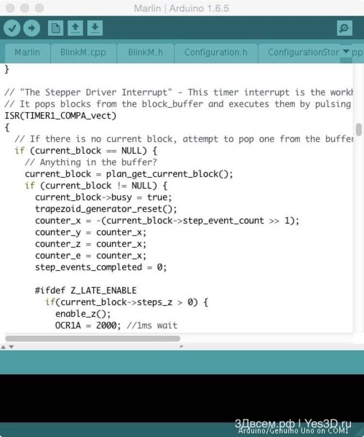
Marlin and Mega: STEP Signal Frequency
Before switching to the second part and start talking about the REPRAP electronics. I want to try to deal with one controversial point - potential problems with microssem 1/32. If theoretically estimate, then on the basis of technical capabilities, its performance platform should not be enough to move at a speed above 125 mm / s.
To check this log, I built " test stand", I connected the logical analyzer, and began to experiment. The "stand" is a classic "Mega + Ramps" sandwich with converted past-headed power, installed one DrV8825 driver (1/32). The engine and current to mention the meaning is not - the results are fully identical to the "full" connection, in the presence of the driver and the absence of the engine, in the absence of both the driver and the engine.
That is, pushing out from the frequency of interrupts in 10 kHz, we get an effective frequency up to 40 kHz. Applying a little arithmetic to this, we get this:
up to 62.5 mm / s - one step to interrupt;
up to 125 mm / s - two steps to interrupt;
up to 250 mm / s - four steps to interrupt.
This is theory. What in practice? And if you set more than 250 mm / s? Well, well, I give G1 X1000 F20000 (333.3 (3) mm / s) and analyzing the resulting. The measured pulse frequency is almost 40 kHz (250 mm / s). Logical.
At speeds above 10,000 mm / min (166.6 (6) mm / s), I stably get dips in tact. On both engines synchronously (remind, COREXY). They will last 33 ms, are approximately 0.1 s prior to the slowdown in speed. Sometimes there is the same failure at the beginning of the movement - through 0.1 after the completion of the speed set. In general, there is a suspicion that it sustainably disappears at a speed of up to 125 mm / s - that is, when 4 steps are not used for interruption, but it is only a suspicion.
How to interpret this result - I do not know. With somehow external influences It does not correlate - does not coincide with communication over the serial port, the firmware is collected without supporting all sorts of displays and SD cards.
Thoughts
1. If you don't try to try something from Marlin, the speed ceiling (1.8 ", 1/32, 20 teeth, GT2) is 250 mm / s.
2. At speeds above 125 mm / s (hypothetically) there is a glitch with a tact failure. Where and how it will manifest in real work - I can't predict.
3. In more complex conditions (when the processor counts something strongly) it will be no better, but rather - worse. As far as the question is for a much more monumental study, because it will have to compare the planned program of movement with actually issued (and captured) with impulses - I will not have enough gunpowder.
Part 2. Step Quartet.
In the second part, it will be about how the previously described microcontroller controls stepper motors.
Move IT!
In "rectangular" printers, you need to move on three axes. Suppose, moving the print head of X and Z, and the table with the model - on Y. This is, for example, the usual, beloved by Chinese sellers and our buyers Prusa I3. Or mendel. You can move the head only by x, and the table - on Y and Z. This is, for example, Felix. I practically immediately as I was in a 3D printing (with MS5, which has a Xy-table and Z-head), so became a fan of the head movement by X and Y, and the tables - along Z. This is kinematics Ultimaker, H-Bot, Corexy.
In short, many options. Let us assume that we have three motors, each of which is responsible for the movement of something on one of the axes in space, according to the Cartesian coordinate system. In the "Push" for the vertical movement correspond to two engines, the essence of the phenomenon does not change. So, three engines. Why in the headline quartet? Because it is necessary to serve more plastic.
In leg
Traditionally, stepper motors are used. Their chip is the tricky design of the stator winding, the rotor uses a permanent magnet (that is, there are no contacts related to the rotor - nothing is erased and does not spark). The stepping motor, according to its name, moves discretely. The most common sample sample has a NEMA17 sizer (in fact, the seat is regulated - the four mounting holes and the protrusion with the shaft, plus two dimensions, the length can vary), is equipped with two windings (4 wires), and its full turn consists of 200 steps (1.8 degrees per step).
In the simplest case, the rotation of the stepping motor is carried out by consistent activation of the windings. Under the activation means an application to winding the supply voltage of direct or reverse polarity. At the same time, the control circuit (driver) should not only be able to switch the "plus" and "minus", but also limit the current-consumed current. Commuccination mode is called full-haule, and he has a significant drawback - on low speeds The engine is terribly twitching, on a little higher - starts growing. In general, nothing good. To increase the smoothness of the movement (the accuracy does not increase, the discreteness of the full steps does not disappear!) The microcal control mode is used. It lies in the fact that the current limit fed to the winding changes via sinusoid. That is, one real step accounts for a number of intermediate states - microchp.
Specialized microcircuits are used to implement micro-drive engines. As part of the reprap, their two - A4988 and DRV8825 (modules based on these chips are usually called the same). Plus, careful TMC2100 begins carefully here. Drivers stepper engines Traditionally, performed in the form of modules with legs, but come and are attacked on the fee. The second option at first glance is less convenient (there is no possibility to change the type of driver, and when there is a sudden hemorrhoid when you exit, it is also available - on advanced boards, program control of the engine current is usually implemented, and on multi-layer boards with normal wiring, sealed drivers Cool through the "Puzo" chip on the heat sink layer of the board.
But, again, speaking about the most common variant - the driver chip on its own footplate with legs. At the input, it has three signals - STEP, DIR, ENABLE. Three more conclusions are responsible for the microgen configuration. We feed or do not supply a logical unit by installing or removing jumpers (jumpers). The logic of the microgen is hiding inside the chip, we do not need to climb there. You can remember only one thing - Enable allows the driver operation, the DIR determines the direction of rotation, and the pulse filed to STEP says the driver says that one microchp must be made (in accordance with the configuration specified by jumpers).
The main difference between the DRV8825 from A4988 - support for the crushing step 1/32. There are other subtleties, but to start it is enough. Yes, the modules with these chips are inserted into the control boards in different ways. Well, it turned out from the point of view of the optimal layout of the module boards. And inexperienced users harness.
In the general case, the higher the value of crushing, the smaller and the engines work quieter. But at the same time, the load on the "NOGOODG" is increasing - after all, it accounts for Step more often. I do not know about problems when working on 1/16 personally, but when there is a desire to switch to 1/32 completely, it may already have a lack of performance "Mega". The mansion here is the TMC2100. These are drivers that take the STEP signal with a frequency as for 1/16, and "imagine" to 1/256. As a result, we have smooth silent work, but not without flaws. First, the modules on the TMC2100 are expensive. Secondly, I personally (on a homemade corexy called Kubocore) with these drivers there are problems in the form of passing steps (respectively, positioning failure) during accelerations above 2000 - with DRV8825 there is no such thing.
Summarizing in three words: each driver needs two microcontroller feet to set the direction and give the pulse of the microchp. The driver's performance permissions are usually common on all axles - the engine shutdown button in Repetier-Host is just one. Microsg is good in terms of smoothness of movements and combating resonances and vibration. Restricting the maximum motor current must be configured using trimming resistors on driver modules. When you exceed the current, we will receive excessive heating of drivers and engines, with insufficient current there will be a passage of steps.
Spotykach
In REPRAP is not provided feedback in position. That is, the program of the controller does not know where this moment There are moving parts of the printer. Strange, of course. But with direct mechanics and normal settings it works. The printer moves everything in front of the print all that is in the initial position, and it is already repelled in all movements. So, the opposite phenomenon of the passage of steps. The controller gives the driver to the driver, the driver tries to turn the rotor. But with excessive load (or insufficient current), the "rebound" occurs - the rotor begins to rotate, and then returns to initial position. If this happens on the x or y axis, we get a layer shift. On the Z axis - the printer begins to "mock" the next layer in the previous one, also nothing good. Often, the skip occurs on the extruder (due to the clogging of the nozzle, excessive feed, insufficient temperature, too much distance to the table at the beginning of the print), then we have partially or completely unsophisticated layers.
With how the passage of steps is manifested, everything is relatively clear. Why is this happening? Here are the main reasons:
1. Too big load. For example, a reared belt. Or peashed guides. Or "killed" bearings.
2. Inertia. To quickly dispersed or brake a heavy object, you need to spend more effort than with a smooth change of speed. Therefore, the combination of high accelerations with a heavy carriage (or table) may well cause skipping steps with a sharp start.
3. Incorrect configuration of the driver current.
The last item is generally the topic for a separate article. If briefly - each stepper motor has such a parameter as the rated current. It is in the range of 1.2 - 1.8 A. in the range of 1.2 - 1.8 A. So, with such a current limitation you should work well. If not, it means that the engines are overloaded. If there is no passage of steps with a lower limitation - in general perfectly. When the current decreases with respect to the nominal, the heating of the drivers decreases (and they can overheat) and the engines (no more than 80 degrees are not recommended), plus, the volume of the "song" of the heads is reduced.
Part 3. HOT.
In the first part of the cycle, I talked about small weak 8-bit AVR architectural microcontrollers AVR, specifically about MEGA 2560, which "taxis" by most amateur 3D printers. The second part is devoted to the management of stepper motors. Now - about heating devices.
The essence of FDM (Fused Deposition Modeling, Brand Stratasys, usually to the light bulb, but the inadequate people came up with FFF - Fused Filament Fabrication) in the layer of filament. The wording occurs as follows: the filament should melt in a certain zone of hotels, and the melt, pushed by a solid part of the rod, is extruded through the nozzle. When moving the print head, simultaneous extrusion of the phylament and the publication of it to the previous layer end of the nozzle occurs.
It would seem that everything is simple. Cool the top of the tube of the thermometer, and the bottom - heating, and everything is fine. But there is a nuance. It is necessary to maintain the temperature of hotels with decent accuracy, so that it walked only in small limits. Otherwise, we obtain an unpleasant effect - part of the layers is printed at a lower temperature (the filament is more viscous), part - with a higher (more liquid), and the result looks similar to Z-vobbling. And so, in our full growth, the question of stabilizing the temperature of the heater, which has a very small inertia, is due to the low heat capacity of any external "sneeze" (draft, the fan of the blower, you never know what else) or the control error instantly leads to a noticeable change in temperatures.
Here we invade the panels of the discipline called Tau (the theory of automatic control). Not quite my specialty (Aytichnik, but I have been released by the ACC Department), but we had the course, with a teacher who showed slides on the projector and periodically eagerly lit with the comments: "Oh, entrusted these students lectures in the electronic form to translate Such jambs stood up, well, nothing, you will figure it out. " Okay, lyrical memories aside, welcome the PID regulator.
I highly recommend getting acquainted with the article, there is quite accessible written about the PID regulation. If it is completely easy to simplify, then the picture looks like this: we have some temperature target value. And with a certain frequency, we obtain the current temperature value, and we need to give the control effect to reduce the error - the difference between the current and target value. The control effect in this case is the PWM signal on the fuel transistor (Mosfta) of the heater. From 0 to 255 "Parrots", where 255 is the maximum power. For those who do not know what PWM is the simplest description of the phenomenon.
So. Each "tact" of working with the heater we need to decide on issuing from 0 to 255. Yes, we can simply turn on or off the heater without biting PWM. Suppose the temperature is above 210 degrees - do not turn on. Below 200 - turn on. Only in the case of hotkend heater, such a scatter does not suit us, you will have to raise the frequency of "clocks" of work, and these are additional interrupts, the work of the ADC is also not free, and we have extremely limited computing resources. In general, it is necessary to manage more precisely. Therefore, PID regulation. P - proportional, and - integral, d - differential. The proportional component is responsible for the "direct" reaction to the deviation, integral - for the accumulated error, differential in response to the processing of the error change rate.
If it is even easier - the PID controller issues the control effect depending on the current deviation, taking into account the "history" and the rate of change of deviation. I infirmly hear about the calibration of the PID regulator "Marlin", but this function is available, as a result we get three coefficients (proportional, integral, differential) allowing you to most accurately control exactly our heater, and not spherical in vacuo. Those interested can read about the M303 code.
To illustrate extremely low inertia hotels, I simply blow it on it.
Okay, it's about Hotend. It is all if it comes to FDM / FFF. But some love jogging, so arises great and terrible, burning mosples and ramps, heating table. From an electronic point of view, it is increasingly harder with it than with hotkend - power is relatively large. But from the standpoint of automatic regulation, it is easier - the system is more inert, and the permissible amplitude of the deviation above. Therefore, the table with the purpose of saving computing resources is usually managed on the principle of Bang-Bang ("Pisch-Pisch"), this approach described above. While the temperature did not reach a maximum, with 100% warmth. Then let him cool to a permissible minimum, and again warm. I also note that when connecting a hot table through an electromechanical relay (and so often do to "unload" Mosfet) only Bang-Bang is a permissible option, you do not need to shimy the relay.
Sensors
Finally - about thermistors and thermocouples. The thermistor changes its resistance depending on the temperature, is characterized by a nominal resistance at 25 degrees and a temperature coefficient. In fact, the device is non-linear, and in the same "Marlin" there are tables to recalculate the data obtained from the thermistor to the temperature. Thermocouple - a rare guest in reprap, but comes across. The principle of action of another, thermocouple is a source of EMF. Well, that is, it gives a certain voltage, the magnitude of which depends on the temperature. Directly to RAMPS and such payments are not connected, but active adapters exist. What is interesting, also in Marlin, there are tables for metal (platinum) resistance thermometers. Not such a rare thing in industrial automation, but whether "live" is found in the REPRAP - I do not know.
Part 4. Unity.
A 3D printer that works on the FDM / FFF principle consists, in fact, out of three parts: mechanics (movement of something in space), heating devices and electronics, and all this control.
In general terms, I already told how each of these parts is working, and now I will try to speculate on the topic "How it is going to one device." IMPORTANT: I \u200b\u200bwill describe a lot from the standpoint of a homemade leafer, not equipped with wood or metalworking machines and operating with a hammer, drill and hacksaw. And not yet to be sprayed, mainly about the "typical" REPRAP is one extruder, a print area around 200х200 mm.
The least variable
Original E3D V6 and its very unreleased price.
I will start with the heaters, there are not very many popular options. Today, in the environment of self-deplets, HOTEnd E3D is most common.
More precisely, his Chinese clones are very floating quality. There will be no separate discipline about tormenting with polishing of the entire metal barrier or the use of the Bouter tube "to the nozzle" - this is a separate discipline. From personal little experience - a good metal barrier works perfectly with ABS and PLA, without a single break. A bad metal barrier works fine with ABS and obscure (right up to "no way" - with PLA), and in this case it is easier to put an equally bad thermobarier, but with Teflon insert.
In general, E3D is very convenient - it is possible to experiment both with thermal charges and with heaters - are available both "small" and Volcano (for thick nozzles and fast brutal printing). Also conditional division, by the way. Now I use Volcano with a nozzle 0.4. And some invent a spacer sleeve, and work well with short nozzles from the usual E3D.
The program is minimum - we buy a typical Chinese kit "E3D V6 + heater + set of nozzles + cooler." Well, I recommend that a pack of different thermobariers immediately, so that when it comes to it, do not wait for the next parcel.
The second heater is not the second hotkend (although it is also not bad, but we will not dive), and the table. It is possible to rank at the Knights of the Cold Table, and at all do not raise the question of the lower heating - yes, then the choice of filament is narrowed, you will have to think a little about reliable fixation of the model on the table, but you will never know about the charred RAMPS terminals, deep relationships with thin wires and Printing defect type "Elephant Noga". Okay, let the heater still be. Two popular options are made of foil fiberglass and aluminum.
The first is a simple, cheaper, but curve and "liquid", requires normal mounting to a rigid design and smooth glass from above. Second
- In fact, the same printed circuit board, only as a substrate - aluminum. Good own rigidity, uniform heating, but it is more expensive.
The non-obvious lack of aluminum table is when the Chinese is poorly susceptible to it thin wires. On the textolite table, replace the wires simply, having basic soldering skills. But soldering 2.5 squares to the pathways of the aluminum board - the task of an advanced level, taking into account the excellent thermal conductivity of this metal. I used a powerful soldering iron (which with a wooden handle and stained in the finger), and he had to call for the thermal-wide soldering station.
The most interesting
The most delicious part is the choice of kinematics. In the first paragraph, the wrapped in the first paragraph mentioned the mechanics as a means of "movement of something in space". Here, now just to the fact that and where to move. In general, we need to get three degrees of freedom. And you can move the print head and the table with the part, from here and all the variety. There are radical designs with a fixed table (delta printer), there are attempts to use the milling machines (XY-table and Z-head) schemes, there is general perversions (polar printers or borrowed from SCARA-mechanic robotics). About all this chaos can be arguing long. So, limit the two schemes.
"Prush"
XZ portal and y-table. Polishly correctly call this scheme "deserved". Everything is more or less clear, a hundred times implemented, doped, modified, put on the rails, in the dimensions it is sabbaged.
The general idea is as follows: there is the letter "P", on the legs of which the crossbar drives, driven by two synchronized engines by means of transmitting the "screw nut" (rare modification - with belts). The engine hangs on the crossbar, which for the belt is tested to the left-right carriage. The third degree of freedom is moving back and forth table. The advantages of the design is, for example, the study along and across or extreme simplicity in the handicraft implementation of the subwoofers. Minuses are also known - the problem of synchronization of engines z, the dependence of print quality is already from two studs that should be more or less the same, it is difficult to accelerate to high speeds (Since there is a relatively heavy inert table).
Z-table
When printing, z coordinate is slower than all, and only one way. So we will move the table vertically. Now you have to come up with how to move the printhead in the same plane. There is a solution to the problem "in the forehead" - in essence. We take the portal "Prounya", put it on the side, replace the studs on the belt (and remove the extra engine, replacing it to the transfer), turn it out 90 degrees hotkend, voila, we get something like a MakerBot Replicator (not the last generation).
How else to improve this scheme? It is necessary to achieve the minimum mass of moving parts. If we give up the direct-extruder and we will feed the pipeline on the tube, the X engine remains, which must be groaned to roll on the guides. And here it turns on the real engineering inlet. In a Dutch, she looks like a bunch of trees and belts in a drawer called Ultimaker. The design is brought to such a level that many consider Ultimaker to be the best desktop 3D printer.
But there are simpler engineering solutions. For example, H-Bot. Two still motors, one long belt, handful of rollers. And this case allows you to move the carriage in the XY plane by rotating the engines in one or in different directions. Handsomely. In practice, there is an increased requirements for the stiffness of the structure, which somewhat complicates the manufacture of matches and acorns, especially when using wooden bearings.
A more complex scheme, with two belts and a greater bunch of rollers - Corexy. I think the best option For implementation, when you have already collected your or Chinese "Push", and the creative itch does not bother. You can do from plywood, aluminum profile, stools and other unnecessary piece of furniture. According to the principle of operation, the result is similar to H-Bot, but less inclined to the jamming and twisting of the frame in the rogues of the horn.
Electronics
If you need to save money, MEGA + RAMPS in Chinese version is simply out of competition. If there are no special knowledge in the electrics and electronics, and the nerves are not extra, it is better to look in the direction of more expensive, but competently made boards from MakerBase or Geeetech.
The main sores of the sandwich in the form of "not those" output transistors and the power of the entire five-walled collective farm through the stabilizer on the Arduino board there are cured. If we talk about completely alternative versions, then I am waiting for the opportunity to purchase a board on LPC1768, for example, the same MKS Sbase, and you have a 32-bit ARM and SMOOTHIEWARE firmware. And in parallel - leisurely study the TEACUP firmware in relation to Arduino Nano and Nanoheart.
Homemade
Well, let's say, you decided to make your bike. I do not see anything bad in it.
In general, it is necessary to repel from financial opportunities and from what can be found in the garage or basement. And from the presence or lack of access to machines and radius of the curvature of the hands. Roughly speaking, there is an opportunity to spend 5 thousand rubles - well, byfeit the minimum. For the top ten, you can already get raised a little, and the budget approximation to 20 thousand is pretty unleashed hands. Of course, it greatly facilitates life the opportunity to buy a Chinese designer "Push" - you can and understand the basics of 3D printing, and get an excellent tool for the development of self-pole.
Moreover, most of the parts (engines, electronics, part of the mechanics) calmly move in the next design. In short, we buy acrylic junk, finish up to the imputed state, print the items for the next printer, let the previous on parts, wash, wash off, repeat.
This is probably all. Perhaps it turned out a little gallop. But in a different way, it is difficult to argue in the framework of the overall review material. Although, useful links for reflections I threw, looking for anyone in any way. Questions and additions are traditionally welcome. Well, yes, in the foreseeable future there will be a continuation - already on specific decisions and rakes as part of the design and construction of Kubocore 2.


Advanced pleasure today are additive printers. Many have to spend not one hundred or even a thousand dollars only in order to purchase this high-tech machine. The way of self-assembly of devices for three-dimensional printing is interested in many. Why not try to print on the printer exactly the same device if the form of the components created can be any? Modern engineers really have the opportunity to collect a 3D printer with their own hands.
Examples of successful assembly
Modern designers are confident that the device for three-dimensional printing should be available to all. In 2004, the mechanisms capable of reproducing themselves were discussed for the first time. It was planned to create installations that print copies of their own components.
The pioneer in this area was able to recreate more than half of these parts. The second generation of devices used for the creation of metal alloys, marble dust, talc and plastic. Such installations could not be called ideal inventions. They demanded refinement.
The basic price of a regular platform for the development of components is 350 euros. Equipment providing the ability to print electrical circuits, worth ten times more expensive. In order to copy such installations, effort will have to make.

How to assemble a 3D printer with your own hands
For self-assembly, the standard Ewaste model is suitable. It costs less than 60 dollars. If you manage to find suitable components that can be removed from unnecessary electrical appliances, it is quite real to collect it. To do this, you will need a NEMA 17 motor, a power supply from a PC, DVD drive, shrink tubes and connectors.
Another design can be collected from component disassembled laser printers in combination with steel guides, metal profiles and plastic bearings. 4 Motors are attached to the frame, two of them must maintain the microgen function. You will also need to use multiple connecting wires, optical sensors and thermostators for the cell. Many users note that they managed to construct a 3D printer with their own hands. Drawings you can see in the article, they are available for familiarization. The usual settings created at home are not endowed with outstanding properties, but they cope with the seal of small plastic products.
Available details facilitate work
There is always the opportunity to assemble something special. The diagram of an inexpensive device for three-dimensional print was proposed by Chinese experts. An open market of components makes it possible to acquire all the necessary components of such a mechanism. Chinese designers applied Makeblock frame, which can be purchased from the company's store.
Now there is nothing complicated in creating a 3D printer with your own hands. The device is completed with an Arduino MEGA 2560 electric board. Management can exercise a regular user. personal computerBy setting the pre-required software.

Each will have to choose the assembly technology. For all generations of modern self-reproducing devices, a rapid development is characterized. The factory assembly printer costs significantly more printed components.
Prospects and small difficulties
Several such astronaut printers plan to capture with them into space in the near future. Loading capacity and the useful area of \u200b\u200bthe aircraft can save thanks to these wonderful devices. Astronauts will have to assemble a 3D printer with their own hands. From the printer involved, for example, on the moon, it may be very good building equipment for the construction of space bases. Small sand will be used as ink.
For modern engineers will not work to make a 3D printer with their own hands. Reprap design make it possible to protect the wallet from unnecessary costs. Ready samples require individual setup. This can negatively affect printability. It should be mentioned that for self-assembly, a lot of patience and considerable knowledge of the engineering business will be required.
The use of exhaust electronics
Not everyone has the opportunity to buy a 3D printer, but many dreams of this device. In order not to throw out money, you can search for suitable components in other electronic devices and use them at the base of a self-made printing device. The total cost of such a printer will not exceed 100 dollars. This is cheap, given what is homemade. The 3D printer can create all lovers who are familiar with the Azami engineering due to the principles described with their own hands.

It should be started with the analysis of the specifics of the work of universal CNC systems. You must learn a list of basic commands to manage the device using a program code. The design of the motor and extruder's power regulator is attached to the design. Each device designed independently will include several main components: housing, power supply, stepper motor, controller, printed head and guides.
Make up the axis of coordinates and prepare the motor
As the parts used at this stage, you can use ordinary drives for CD / DVD, remaining from old computers. You will need a floppy drive. At this stage, you should make sure that the drive motors do not work from direct current, and step by step. Of all the existing engines necessary in order to mount a 3D printer with their own hands, NEMA 23 is the best option when used in the plastic extruder.
Extra electronics will also be required, the choice of which will depend on the financial capabilities and its availability. It is necessary to prepare all cables, power supply, heat-resistant tubes and connectors. Wires are soldered to stepper motors.

We pay attention to the extruder
Drives for plastic fiber will be mounted from the MK7 / MK8 gear and step-down Motor NEMA 23. You also need to download software to control the elements of the printing extruder. Also do not forget about the drivers.
Plastic material will be drawn into an extruder and enter the heating compartment. Then the heated ink pass through heat-resistant tubes. To assemble a direct drive, you need to connect the mount on the frame with a stepper motor. The resulting data on the extruder is set in the Repetier program. Such a 3D printer makes it yourself under the power of any engineer.

Testing
Cooking the device to the first test can be considered completed. The diameter of plastic fiber in the extruder should be 1.75 mm. Such thickness will not require large number Energy during printing. It is recommended to fill the PLA-plastic in the printer due to lightweight, safety and simplicity in the use of this material.
Repetier is activated and skeinforge profile sections are running. To check the calibration, you can print any simple figure. If the assembly has been carried out incorrectly, configuration problems can be detected almost immediately by checking the size of the product obtained.
To get started, you must open the STL model, define the shape for printing, enter the appropriate G-code. The extruder is rapidly, and then starts to melting plastic. It is necessary to squeeze some material to verify the device. The above instruction describes the basic principles of work that must be adhered to to make a 3D printer with their own hands.
Conclusion
Today, every engineer understands that the device for 3D printing is quite realistic to create independently. At the stage of collecting information, no difficulties will arise. We described the entire procedure in detail above.

To successfully implement the task, you need to understand the technology of making the device and determine the main problems that you have to cope. It is necessary to get a drawing (see above), choose all components, make a lot of work and learn a considerable amount of additional information. Results will definitely please.
Such a device can create figures of small sizes, and practical benefits will be a bit from it, but each engineer with a sufficient level of information support is capable of collecting such installation. Someone may seem an exciting process, and not the products themselves. If the engineer wants to make a 3D printer with his own hands for the manufacture of large parts, in any case will have to fork out, because the components for such devices are much more expensive. Those who have no problems with the means will have to face with the search for the device necessary for self-assembling a large printer. Successes!
An independent creation of an additive printer is a time-consuming process. Such a device will not work in one evening, and its setting can also take extra time. The cost of assembly in the independent magnificent order of components may exceed the price of the budget 3D printer, manufactured factory. But putting some effort and familiarizing yourself with the assembly recommendations, you can create a 3D printer with your own hands, and it will be perfect for your needs.
Selection and purchase of parts
The 3D printer assembly will cost you cheaper than just if you order parts in Chinese online stores. The most popular site on which you can find the entire set of components - Aliexpress. To form a list of components, decide on the design of the future device. If you do not have experience in creating such devices, use thematic forums to search for the list of components and sequences of their assembly with your own hands. In the absence of certain elements - they can be replaced with others, subject to compatibility of characteristics.
Whatever the selected design, you will need a standard set of main components:
- A set of wires and screws to assemble a 3D printer with your own hands.
- The case of the apparatus or metal frame for open-type printers.
- 12V power supply.
- Electronics kit (often Arduino Mega 2560 R3 + stepper drivers).
Note! To save when buying on Aliexpress, use CashBack sites. A fixed percentage of each purchase will be returned to a personal account after order confirmation. You can withdraw money from this account to a map or wallet of the electronic payment system.
Assembling corps
To make a three-dimensional printer housing, any material of sufficient hardness supplied in sheets is suitable. First of all, you should simulate the design or find a ready-made scheme on the Internet. After that, you can proceed to cut out individual parts. If there is an electrolovka or other cutting tool, such work can be performed independently. If there are no necessary tools, it is recommended to order laser cutting services.
To work with ABS-plastic, a closed device design is preferred, which retains high temperature in the chamber. The rapid or uneven frosting of such plastic can cause cracks or lead to the precipitation of the printed model. If you plan to use a print printer using a polylactide (PLA), use an open body or refer to its opening. Printing this type of plastic requires removal of heat and constant cooling.

For the 3D printer housing, 6 mm thick sheets are suitable. Depending on the material selected, they can be transparent or not. With insufficient rigidity, install aluminum or steel corners on the sides. You can also make a housing from a small telecommunications cabinet or other subject. If there is a second 3D printer, the details of the housing of the new device can be printed on it. The most popular materials used to create a frame with their own hands:
- Plywood;
- Monolithic polycarbonate;
- Acrylic.

Important! The housing from plywood is good extinguishing vibration arising when printing.
Installation of parts and final assembly
After making the case, you need to install the components of the printer and adjust the operation of the electronics. When assembly, it is important to comply with the correct sequence of installing parts. Consider that the device can show vibration during the device. All screws must be well tightened, and the main components of the device must be firmly fixed. At the end of the assembly, swipe print on the created 3D printer.

It's important to know! As a rule, the final cost of the 3D device made by hand is 20-30 thousand rubles.
Training video: 3D printer do it yourself for $ 155
See also:
 Coffee printer: types and features of printing devices on coffee foam
 How to connect a printer to a computer: Overview of ways to connect home devices
Ivan Zarubin
IT specialist, DIY starter.
I will not paint all the benefits and all the features of 3D printing, I will just say that this is a very useful thing in everyday life. It is pleasant to sometimes realize that you yourself can create various items and repair the technique in which plastic mechanisms are used, various gears, fasteners ...
Immediately I would like to make clarity - why it is not worth buying a Diemal Chinese printer for 15 thousand rubles.
As a rule, they go with acrylic or plywood enclosures, printing parts with such a printer will turn into a permanent control of the hardness, calibrations and other events that darken the entire charm of the printer.
Acrylic and wooden frames are very flexible and lungs, when printing at elevated speeds, they are seriously sausage, due to which the quality of the final details leaves much to be desired.
Owners of such frames are often collective farming various amplifiers / seals and constantly make changes to the design, thereby killing their time and mood to engage in print, and not refinement of the printer.
Steel frame will give the opportunity to enjoy the creation of parts, and not a struggle with the printer.
Following my small leadership, you will not order too much and do not burn your first set of electronics, as I did. Although it is not so scary: the cost of parts and spare parts to this printer is kopeck.
The manual is designed mainly to beginners, the 3D printing guru is likely to not find anything new here. But those who would like to join, after the assembly of such a kit will clearly understand what. It does not require special skills and tools, sufficient soldering iron, a set of dumping and hexagons.
The cost of components is relevant for January 2017.
Order details
1. The base for the printer is a frame than it is stronger and harder, the better. Heavy and strong frame will not sausage when printing at elevated speeds, and the quality of the parts will remain acceptable.
Cost: 4,900 rubles per piece.
Frame comes with all necessary fasteners. Rogs and buckets guys are put with a margin.
2. Guide shafts and studs M5. Threaded studs and guide shafts do not go bundled with the frame, although they are in the picture.
- Polished shafts go with a set of 6 pieces.
Cost: 2,850 rubles per set.
Perhaps you will find both cheaper. If you search, then choose necessarily polished, otherwise all the shoals of the shafts will affect the details and general quality.
- M5 studs must be purchased by a pair.
Cost: 200 rubles per piece.
It is essentially ordinary studs that can be purchased in a construction store. The main thing is that they are as smoother as possible. Check notes: you need to put the stud on the glass and roll it on the glass, the better riding, the more stripping. Shafts are checked by the appropriate way.
In general, we don't need anything more from this store, for there is a wild markup on the same thing that can be purchased from the Chinese.
Complete value: 1,045 rubles.
Ramps 1.4 - Expansion Board for Arduino. It is all the electronics that the drivers engines are inserted into it. For the entire strength of the printer, she answers. There is no brains in it, there is nothing to burn and break in it, you can not take a spare.
Arduino Mega 2560 R3 is the brain of our printer, which we will pour the firmware. I advise you to take a spare: it is easy to burn it easily, for example, inserting the incorrect drive engine driver or confuses the polarity when connecting the terminal. Many are faced with this, and I also. In order to you did not have to wait a new one, take at least one at least one.
Stepper drivers A4988 are responsible for the operation of motors, it is advisable to purchase another set of spare. They have a construction resistor, do not twist it, perhaps it is already exposed to the necessary current!
- Spare Arduino Mega R3.
Cost: 679 rubles per piece.
- Spare drivers stepping motor A4988. I advise you to further take another spare set of 4 pieces.
Cost: 48 rubles per piece.
Cost: 75 rubles per piece.
It is necessary to protect our Arduino. It has its own downstream regulator from 12 V 5 V, but it is extremely capricious, heats greatly and quickly dies.
Complete value: 2 490 rubles.
Included 5 pieces, we need only 4. You can search for a set of four, but I took the whole set, let it be one spare. It will be possible to put it on the upgrade and make the second extruder to print support for the second extruder or two-color parts.
Complete value: 769 rubles.
This set has everything you need for this printer.
Cost: 501 ruble per piece.
In its back there is a cartrider in which in the future you will insert a memory card with print models. You can take one spare: if you incorrectly connect some element, then, most likely, the display will dhink the very first.
If you plan to connect the printer directly to the computer and print from a computer, the screen is completely optional, the print can be made without it. But, as practice has shown, it is more convenient to print with the SD card: the printer is not connected to the computer, it can be put at least to another room, without fear that the computer will hang or you are inadvertently cut down in the middle of the print.
Cost: 1 493 rubles per piece.
This power supply is slightly more in size than the one that should be, but it is without much work climbs, and its power with a margin.
Cost: 448 rubles per piece.
We are necessary for printing ABS plastic. To print PLA and other types of plastic that do not give shrinkage when cooled, you can print without a heating platform, but the table is required, glass is put on it.
Cost: 99 rubles per piece.
Cost: 2,795 rubles per piece.
This extruder is a direct-extruder, that is, the plastic supply mechanism is directly in front of its heating element. I advise you to take this, it will allow you to print with all kinds of plastic without special stages. Included there is everything you need.
Cost: 124 rubles per piece.
Actually, it is necessary for blowing PLA and other slowly solidifying plastic species.
Cost: 204 rubles per piece.
Very needed. A greater cooler will significantly reduce the noise from the printer.

Cost: 17 rubles per piece.
When clogged, it is easier to change the nozzle than to be cleaned. Pay attention to the diameter of the opening. Alternatively, you can dial different diameters and choose for yourself. I preferred to dwell on 0.3 mm, the quality of the obtained parts with such a nozzle is enough for me. If the quality does not play a special role, take the nozzle wider, for example 0.4 mm. The print will be at times faster, but the layers will be more noticeable. Take several at once.
Cost: 31 ruble apiece.
It is very easy to break, be careful. You can not take the drill: easier, as I wrote above, gain spare nozzles and change them. They cost a penny, and clogged extremely rarely - when using normal plastic and with the presence of a filter that you will print first.
Cost: 56 rubles per piece.
Included 5 pieces, 4 Use the table, one spring for the X axis limiter.

The assembly process is quite fascinating and something resembles the assembly of the Soviet metal designer.
We collect everything according to the instructions except for the following items
In paragraph 1.1, at the very end, where end supports are attached, we do not put the Bearings 625Z - however, we did not order them. We leave the running screws in the "free swimming" in the upper position, it will save us from the effect of the so-called vobble.

Paragraph 1.4 in the picture there is a black spacer. Included with the frame there is no, instead there are plastic bushings, we use them.
In paragraph 1.6, the router of the axis of the Y axis is not to the rear, but to the front wall of the printer. If this is not done, the details are printed mirrored. As I tried to win this in the firmware, I failed.
To do this, you need to repaid the terminal on the back of the board:

In paragraph 2.4, we have another extruder, but it is attached in the same way. For this, we need long bolts, we take them from the kit to adjust the table (18th position in the list). In the set with the frame there are no such long bolts, as in local stores.

In paragraph 2.6, we start assembling our "sandwich" from Arduino and Ramps and immediately make a very important refinement, which is rarely writing in manuals, but which is nevertheless very important for further uninterrupted printer.
We need to untie our Arduino from nutrition, which comes from the RAMPS card. To do this, drop or cut off the diode from the RAMPS card.

We solder the voltage regulator to the input of the power supply, which in advance exhibit on the 5 V in advance, having fallen a standard power socket. We glue the regulator who is much more convenient, I glued to the back wall of the Arduino itself.

Power supply from the power supply to the RAMPS, I soldered separately to the legs to leave a free terminal to connect other devices.

Before starting, check that anywhere does not start anything, the carriage moves to the limiter and back without obstacles. At first, everything will move tight, over time the bearings will proverb and everything will go smoothly. Do not forget to lubricate guides and hairpins. I lubricate silicone lubricant.
We are looking again that anywhere does not close anything, the drivers of stepper motors are delivered correctly according to the instructions, otherwise it burns and screen, and Arduino. The limiters also need to put observing the correct polarity, otherwise the voltage stabilizer on Arduino will burn.


Preparation for exploitation
If everything is connected correctly, you can go to the next instruction manual.
Useful materials for some parameters of our firmware
- My configured and working version of the firmware for this printer and extruder. It is slightly calibrated under the details that we ordered.
We fill the firmware via the IDE Arduino 1.0.6, select on the Auto Home printer screen, we make sure in the correct connection of the contacts and the correct polarity of the heads. If moving in the opposite direction, simply turn the terminal at a motor 180 degrees. If after the start of the movement, the opposite squeak is heard, it is a peak of the heads of the heads. It is necessary to twist on them a trimming resistor according to the instructions.
I advise you to start printing from PLA-plastic: it is not capricious and sticks well to Xeno Scotch, which is sold in construction stores.
I take Plastic Bestfilament. I took the company REC, but I did not like how the layers fall. There is another sea of \u200b\u200bvarious brands and types of plastic: from rubber to "wooden", from transparent to metallized ... Another firm that I will recommend - Filamentarno. They have chums and a great own type of plastic with excellent properties.
ABS and HIPS plastic I type in the caputon scotch, smeared by the usual pencil glue from the stationery store. This method is good because there is no smell. There are many others in different ways Enhance adhesion details to the table, you will know about it yourself in the process of samples and errors. Everything is achieved by experienced, and everyone chooses its way.
Why is this printer based on Prusa i3?
- Printer "omnivore". You can print by any available plastic species and flexible rods. Today, the market of various types of plastic is sufficiently developed, there is no such need to have a closed boxing.
- The printer is easy to build, configure and maintain. Cooking with him can even a child.
- Sufficiently reliable.
- Distributed, respectively, in the network of the sea information about its configuration and upgrades.
- Suitable for upgrades. You can order a second extruder or an extruder with two printed heads, replace linear bearings to caproolone or copper sleeves, thereby raising print quality.
- Available for money.
 Filter for filament
 Printed fastening for E3D V6 extruder, printed for a while by this extruder with a bouter-feed. But returned back to MK10.

Acquired here such an upgrade, in the future we will print two plastics.

The table was insulated for faster heating: a substrate with a reflective foil layer and adhesive base. In two layers.

Made the backlight from the LED tape. At some point it was tired of including light to control the print. In the future, I plan to secure the camera and connect to the Raspberry PI printer for remote observation and sending models to print without twist flash drive.
If you have children, this designer will be very useful and interesting. To attach children to this area will be easy, they will be in the kayf to print various toys, designers and smart robots for themselves.
By the way, children's technoparks are now actively opened in the country, in which children teach new technologies, including modeling and three-dimensional printing. Having such a house printer will be very useful for a passionate child.
If I had such a thing in my childhood, my happiness would not have a limit, and if you add various motors, Arduino, sensors and modules, I would probably have a roof from the possibilities that would be opened before me. We instead melted plastics from old toys and lead from the batteries found on the garbage.
Everyone who decides to repeat, wish you a successful assembly and the rapid arrival of the goods ordered. :)
Thank you for your attention, if you have questions, ask.
A very useful Russian-language resource on which you will find any information in this area:
Most modern devices and gadgets that are interesting to their functionality - we do not "afford." There are also cases and aggregates for 3D printing. The device gives enormous opportunities for work and entertainment, but its cost is quite high. So many and think: how to assemble a 3D printer with your own hands? We present practically step-by-step instructions Assembly.
As an example, take a set "Mosaic" from company "MakerGear". In fact, it is a designer, it is clear to it, it is clear drawings and instructions. Armed with a simple tool we begin to build.

We take the drawing, fold the printer frame and fix it with bolts and screws that are included in the kit. The carcass assembly will take two hours, depending on your skills. The frame itself consists of nine parts cut from birch, and spare parts are logically suitable for each other (labeled). The first half an hour seems that spare parts are very fragile, but it is not worth worrying.
We will need hexagon screwdrivers and pliers for clamping some bolts. The slots in detail can be clogged with chips, so it will be necessary to clear it in order to clean them. In principle, the design looks confident enough.

The next step-montage on the design of the frame axis "X" and "Y" for the platform of the moving head. Each axis is fixed by a motor serving for belts moving component by plate. The axis "X" is attached to the top of the printer and leads to the extruder. The axis "Y" is fixed to the wooden structure, leading to the movement on which plastic is enjoyed while working.

With the help of Ostrogubs, we connect the motor with the rails, nothing complicated. The belts had a little tinker. It is necessary to pay tribute to MakerGear, which packed the belt already collected. The complexity was only in their stretch.

The homemade printer gradually began to acquire its recognizable outlines. We will not describe the minor details of this stage. The main thing is to be done: installation of the axis "z" and its rod support; Install moving the extruder head; connect platforms with heating elements; Connect the wires with the power supply, heating parts and temperature sensors. By the way, the construction assembly reminded the installation of computer parts, so do not worry - everything is not as scary, as it seems.

An important point - the platform must be evenly installed. To achieve this, you need to move the head at all corners of the platform until you make sure that in all positions of the distance extruder, to the platform are equal.

The hardware is collected, the following step will be the installation of software (software) and the 3D printer calibration.

The installation process of software takes longer than the frame assembly. The manufacturer makes special instructions, permanent updatesDrivers helping to connect a computer with a printer. As for software, they set Cube 3D, as the manufacturer assured that this is the optimal program for the consumer.

By installing software, continue - Pronterface and SkeinForge programs. The first program is used to control the work. It translates STL and OBJ files to a real object. She can be controlled by all axes, platform and extruder.
SKEINFORGE - Allows you to change the 3D printer settings: affect speed, print time, form parts and much more. The program is interesting and powerful, but it is quite difficult for it.

Calibration has passed without problems. You can start printing first models.
We wanted to print a difficult geometric shape, and something more complicated, for example, an octopus model. There are practically no problems with printing: the clamp on the platform interfered with the movement of the extruder. Decided by replacing the stationery clamp with an insulating tape.

In the end, despite we managed to get the cherished figure of the octopus.

As practice has shown to collect 3D printer, do it yourself quite real, but you have to sacrifice your time and be extremely neat. If there is no time and the 3D printer is needed, it is better to buy a collected model.


