The development of domestic army radio stations from the thirties to the present day.
To understand the importance of radio in modern warfare, it is necessary, first of all, to imagine the role of radio communications in command and control. With the emergence of mass armies and the growth of their technical equipment, with the increase in the length of fronts and the range of weapons, the task of coordinating the actions of units at all levels came to the fore. And from these positions it is simply impossible to overestimate the role of radio. It suffices to cite a few figures.
At the final stage of the Battle of Stalingrad in 1942-43. about 9,000 radio stations of various types were involved from the USSR, and 27,174 radio stations simultaneously participated in the operation to liberate Belarus from the German invaders.
Unfortunately, in the prewar years, the People's Commissariat of Communications of the USSR and the Communications Directorate of the Red Army did not provide the proper number of special enterprises that produced communications equipment. The industrial production of radio communications was very low-power.
In the USSR there was a single plant "Krasnaya Zarya", which produced and supplied the country with telephone equipment of all types. There was a factory. Kulakov, who made telegraph devices ST-35 and Bodo, i.e. provided telegraph communications, and the plant them. Comintern, who made powerful radio equipment. Thus, by the beginning of the war with Germany, due to the insufficient capacity of the communications industry, it was not possible to carry out the planned program for re-equipping the communications troops with everything necessary. However, interesting means of communication were still present.
Shortwave radio stations 6PK, 5AK, 11AK, 71TK were created for the army, but the mobility of troops grew, and reliable and economical field stations were required. It was such a RB station (battalion radio station) that was created in 1936. It had a wide frequency range, worked on different types of antennas and provided twice the communication range as its predecessor 6PK. Since 1938, the serial production of the RB began, and already in 1940 they began to modernize it.
Despite the outbreak of war, one of the factories evacuated to Siberia already in 1942 began to produce a modernized RBM station. Two designs were produced: RBM-1 with an output power of 1 W and RBM-5 with a power of 5 W. The stations were equipped with remote devices that made it possible to negotiate from points remote up to 3 km, thanks to which the RBM began to be used as personal radio stations by the commanders of divisions, corps, and armies. The station provided communication up to 30 km when working on a pin, and when working with a "reflected beam" - up to 250 km in the range of 50-200 m.
With the beginning of the war, in connection with the evacuation of factories, the production of RB was temporarily stopped, which sharply worsened the position of the armies. One of the NPO factories in 1942 began the production of primitive 13R radio stations from parts of a mass pre-war 6N-1 receiver. The stations were mounted in plywood boxes covered with tarpaulins. The release of "surrogate" stations 13R continued after the resumption of production of RB, then RBM. The front demanded more and more radio stations.
Stations RB and RBM, created for infantry and artillery, were widely used in other branches of the military, and taken out of production, they served for a long time after the end of the war to geologists, meteorologists and educational organizations of DOSAAF.

By the beginning of the forties, one of the most difficult tasks was to organize communications for the lower level of the army - a platoon, tank, battery, etc. The available stations of the Republic of Belarus and the Republic of Belarus did not satisfy in terms of volume, weight and efficiency. They were transported in two packages and required two people to serve. But that was not even the main drawback. Ground radio stations were required by orders of magnitude more than any other, and, working on the shortwave range in the conditions of large operations, they clogged the air so much that the range became almost impassable.
The way out was found in the development of the VHF band. In 1940, the A-4 ultrashortwave radio station was created, the tests of which gave super-expected results. Working with an amplitude-modulated signal at a transmitter power of 1 W, the station provided a stable connection for 8 km. On the basis of the A-4, in the fall of 1941, the development of the first VHF radio station with frequency modulation, the ten-tube A-7, began. The A-7 stations began to enter the troops in the autumn of 1942, and at the end of 1943 their output reached 1000-1200 sets per month. The station was constantly being modernized, and at the beginning of 1944, the A-7-A appeared, in which the number of lamps was reduced and energy consumption was reduced by 30%. In December 1944, the A-7-B appeared, which had a greater range. In it, for the first time in portable stations, an antenna of the "traveling wave" type was used.
At the beginning of the war, with the organization of the partisan movement, a large number of small-sized and economical radio stations were urgently needed, and the production of portable stations "Sever" and "Sever-bis" was started. The release of the Sever radio station, which became legendary among partisans and intelligence officers, began in Leningrad in July 1941 at the plant named after. Kozitsky. With the evacuation of the plant, production ceased, but in December 1941, already in the besieged city, production was resumed on the remnants of factory equipment and continued until the end of the war. And here the details of the pre-war 6N-1 receiver came into play.
Station "North" was the easiest of all available at that time. Its weight ranged from 6.5 to 10 kg, which depended on the batteries used, while the station itself, made with only three lamps, weighed only 2 kg, the spare property weighed the same amount. She worked in the short wave range and could establish communication with the main receiver with a directional antenna up to 700 km.
In general terms, the development trends of new radios over the years:
Reducing energy consumption.
- Reduced weight and size.
-Expansion of the frequency range.
-Reducing the inter-channel distance.
-Frequency shaping synthesis
-Improve reliability
In recent years, new tasks and functions have also appeared:
Technical speech masking
- Software tuning of radio frequencies (PFC)
-Adaptive radio
-Ability to receive / transmit data.
In addition, sometimes there was a need for radio stations with an extended frequency range. These radio stations use, if necessary, radio communications with civilian structures (police, firefighters) and interaction with aviation and the fleet.
Portable radios have a power of up to 10 watts and are designed to provide radio telephone communication between individual officials (individual) or groups of people limited in number. Communication range - from a few to hundreds of kilometers. The most acceptable section of the frequency range is 5-100 MHz, as it satisfies the intended purpose of radio stations and has a large frequency capacity. The main requirements for portable radio stations are:
Minimum dimensions and weight
-Ease of Management
- work reliability.
The dimensions of radio stations are largely determined by its main characteristics, such as transmitter power, receiver sensitivity, frequency range, etc.
All wearable post-war radio stations can be conditionally divided into TZU radio communications:
1 generation: R-104, R-105, R-106, R-108, R-109, R-116, R-126;
2 generations: R-147, R-148, R-107M;
3 generations: R-157, R-158, R-159, R-143;
4 generations: R-162-xxx, R-163-xxx - "Crossbow" complex
5 generations: R-168-xxx - Aqueduct complex
The generation of post-war radio stations had higher performance characteristics. They were not only fast in terms of telegraphy speed, but also had a method of searchless and tuningless tuning to a radio node, which made it possible to reduce the duration of radio communication sessions by an order of magnitude and thereby further increase its invulnerability.
 The radio stations R-350 ("Eagle"), R-353 ("Proton"), R-354 ("Bumblebee") were developed and put into service. At first, the Eagle was most actively used. The performance characteristics of the station made it possible to conduct radio sessions with front-line reconnaissance radio stations equipped with appropriate central equipment. The complexes of radio nodes made it possible to automatically tune transmitters and receivers to 10 pre-prepared radio frequencies, which significantly reduced the time of communication sessions and accelerated the passage of information. The text of information was accumulated on a standard photographic film (35 mm) and transmitted at a speed of 150 groups per minute.
Along with the use of radio stations R-353 / R-354, during the fighting in Afghanistan, reconnaissance groups used HF radio stations P-143 and Angara 1?, VHF radio stations R-352 / R-392 and R-159.
Given the widespread use of short-wave telephone communications in Afghanistan in special intelligence, it became necessary to develop a special small-sized radio station "Severok-K", which works as a telephone with technical closure of speech information at a distance of up to 150-200 km. It also has stringent requirements for weight and size characteristics and ease of control.
The types of radio signals used have changed significantly. The first generation of radio stations mainly used AM radio signals. Second-generation radios also used AM radio signals to work with the old fleet radios. However, the main type of modulation has become single-sideband modulation (SW). In telegraph mode AT and TH. In radio stations of the third generation, the main type of modulation is FM. The equipment of high-speed performance began to be applied. In addition, some radio stations provide for the possibility of using speech maskers (R-143) and ZAS equipment of guaranteed durability (R-159M). Radio stations of the fourth generation (of the Arbalet complex) ensure operation with ZAS equipment of guaranteed durability.
In the 80s, within the framework of the Nizina-Arbalet research project, the Voronezh Research Institute of Communications developed and tested mock-ups of an adaptive automated VHF radio communication system, which were taken as the basis for the development of interference-proof radio communication equipment of the 4-generation Arbalet TZU. The Arbalet complex for the first time included radio stations from portable and wearable products to portable tank radio stations and powerful HF and VHF radio stations. Especially for the products of the complex, a number of microassemblies were developed, which made it possible to realize the high technical characteristics of the products in the given weight and dimensions and energy consumption. A number of models of radio stations from 1983 to 1987 were adopted.
The radio stations of the Arbalet complex (under the general code - R-163) were supposed to replace almost the entire fleet of existing low-power radio stations. But the collapse of the Union did not allow to complete this work.
Since VHF portable radios are designed to provide communication over relatively short distances, they widely use the meter wave range. Most modern radio stations operate in the 20 to 90 MHz band, which has certain advantages over other bands. The conditions for the propagation of radio waves in this area do not depend on the state of the ionosphere, time of day and year. Here, the level of station interference is much lower, since meter-range radio waves propagate along the earth's surface at distances limited by the line of sight between the receiving and transmitting antennas. And also antenna devices are more efficient and have the largest geometric dimensions.
The most appropriate type of signal for providing VHF radiotelephone communications is FM, which has the best noise immunity. The use of OM is impractical, despite its advantages, due to the complexity of the transmitter and receiver circuits, which causes an increase in size and weight. All modern VHF, portable radio stations are carried out according to the transceiver scheme. They assume the use of the same stages and circuit elements, both in the transmitter and in the receiver.
The use of joint circuits makes it possible to reduce the dimensions and weight of the VHF radio station, reduce the energy consumed from power sources, and simplify the process of setting up and operating the radio station. However, in this case, such radio stations are only simplex.
IN Lately there has been a trend towards expanding the frequency range of portable radio stations.
In the 1990s, the development of the fifth-generation communications complex "Aqueduct" began, which is designed to provide automated closed radio communications in the short-wave and ultra-short-wave bands at the tactical control level. A set of portable, wearable and transportable radio communication equipment R-168 was created with an output power of transmitters from 0.1 to 100 W with reconnaissance and noise-immune modes of operation (AAS, frequency hopping at a speed of 100 hops per second). It has an extended frequency range up to 108 MHz with cryptographic information protection, time division of channels, providing simultaneous transmission of voice messages and data.
VHF radio facilities of the R-168 "Aqueduct" complex are designed to provide stable radio communications in difficult operating conditions in all units and units from a soldier to a division commander in the frequency range from 30.0 to 108 MHz.
Communication facilities of the Granit complex (R-169) are currently being developed.
 Portable (mobile) radios are subject to the same requirements as portable radios. The only exceptions are the requirements for limiting the weight of the radio station, the requirements for dimensions remain one of the main ones. The requirements for the communication range provided by VHF portable radio stations usually range from 20 km to a standard antenna and, by HF radio stations - from 50 km. Portable radio stations are carried out according to the transceiver scheme and, therefore, are simplex, wide-range in them is achieved by dividing the frequency range into sub-bands. Portable radio stations have a transmitter power of more than 10 watts.
ACS (antenna matching device or antenna tuner) performs the functions of an antenna circuit, i.e. provides:
efficient transmission of energy from the antenna to the receiver or from the transmitter to the antenna, pairing the unbalanced PA output with a balanced antenna, filtering harmonics (noise).
The receiver of the radio station is usually performed according to a superheterodyne circuit with one or two frequency conversions.
In low-power radio stations, two options for operation are possible:
1 - with the receiver turned off when transmitting.
2 - with the receiver turned on when transmitting.
The second option is due to two reasons:
1 - a high frequency of the receiving path is used in the AFC system of the exciter.
2 - in the transmission mode, the receiver provides self-listening to the operation of its transmitter.
In some versions, portable radio stations are equipped with an additional receiver, with which you can expand the possible types of radio communication (duplex, etc.).
In order to ensure the operational tuning of the radio station from one frequency to another, the portable radio stations are provided with a system of “Prearranged Frequencies” (PRF). The ZCH system is a device for mechanical (electronic) storage of the position of the adjustment elements (voltages). Tuning from one frequency to another is done automatically by means of electric motors (electronic commutators).
Portable radio stations use the object's on-board network as a power source, as a rule - acid batteries. As additional power sources, it is possible to use petrol-electric units or a 220V network.
All portable radio stations can be conditionally divided by years of production into radio communication equipment TZU:
1st generation: R-112, R-113;
2nd generation: R-111, R-123, R-130;
3rd generation: R-134, R-171, R-173;
4th generation: complex "Crossbow"
5th generation: Aqueduct complex
Comparing the main characteristics of radio stations, we can draw the following conclusions:
1- The communication range of radio stations of all types has not practically changed, since this characteristic is determined by the control link in which this radio station is used. Accordingly, the output power of the transmitter for all radio stations is approximately the same.
2- Antennas also remained virtually unchanged. The main antennas used in portable radio stations of low power TZU are whip antennas (ASh) (including those on telescopic masts).
3- The types of radio signals used have changed significantly. The first generation of radio stations mainly used AM radio signals. Second-generation radios also used AM radio signals to work with the old fleet radios. However, single-sideband modulation (SW) became the main type of modulation for HF radio communications. In telegraph mode AT and TH. In portable radio stations, starting from the first generation, the main type of modulation is FM. From the third generation, high-speed equipment began to be used. In addition, some radio stations provide for the possibility of using speech maskers and ZAS equipment with guaranteed durability. Radio stations of the fourth generation (of the Arbalet complex) ensure operation with ZAS equipment of guaranteed durability.
The modes of operation of radio facilities have changed significantly. In radio stations of 1,2,3 generations, the main modes were simplex and standby reception. The fourth generation radio stations provide for the “duplex”, “scanning reception” (for sequential control of the RFP), “signal-code communication”, “data transmission” (to ensure communication security) operating mode. In radio stations of the fifth generation, in addition to the above, an economizer mode is provided: the radio station is switched on periodically in the receive mode for 2 seconds with an interval of 10 seconds. When receiving a tone call from a correspondent, the radio switches to conventional mode reception. Speech maskers are built directly into radios of this generation.
The number of ZCH in the process of modernization of low-power radio stations has increased. In radio stations of the first generation, there is no ZCH, and in the radio stations of the Arbalet complex, their number reaches 16.
By the beginning of the Second World War, radio communications in the USSR Air Force were either absent or used very little, one of the reasons was that the commanders of the Red Army did not have the necessary skill to use radio communications.
At the beginning of the war, our newest fighters found themselves with practically no radio communication between themselves, the command posts of the air regiments, as well as the VNOS (Air surveillance, warning and communications) posts, not to mention the air controllers in the ground forces. For the most part, without radio communications, the fighter regiments of the Air Force entered combat operations in June 1941.
A good example is the situation with the Yak-1 fighter: despite the decree prescribing “from January 1, 1941 to produce all serial Yak-1s with the RSI-4 radio station?, About a thousand Yak-1s managed to be released without a radio station.
The absence of radio communication equipment on Soviet fighters practically deprived commanders from the link and above of the opportunity to control the combat operations of their subordinate pilots in the air. The inability to maintain radio contact between themselves and the command posts forced the pilots to ignore modern tactical methods of warfare and, against all odds, fly in tight groups, within sight of visual signals.
Yu. Mukhin and A. Lebedintsev in the book "Fathers-Commanders", about a year before the war, radio stations from fighters were removed and sent to warehouses. Historians explain this decision by the fact that the aircraft engines of the USSR aircraft were not shielded, and a crackling sound was heard from the ignition system in the headphones, which distracted the pilot.
VF Golubev, by the way, also talks about the same reason - a strong crackle in the headphones.
Arkhipenko F. F., who fought on the LaGG-3, also refers to the crackling in the headphones, in particular, and says that “... There was a walkie-talkie on the LaGG-3, but it crackled so much that after taking off the headphones, it took another three hours was to come to himself.
Here is what Rybalko V.V., who fought from 1941 to 1943 on the MiG-3, says in response to the question of how things were with radio communications:
“In 1941, there was no radio 42. Even if there was, they weren't used much."
The problem was the lack of an integrated approach to the implementation of noise immunity, that is, with satisfactory characteristics of the radio stations, improper installation of the radio station and insufficient shielding from the interference that the motor created led to incorrect operation of the radio.
Only by 1944, the USSR Air Force was equipped with jamming-proof radio communications at an acceptable level.
The practice of using aircraft for long-distance flights, the rapid development of passenger and cargo transportation by air, and especially the combat experience of using aviation in World War II required that almost all aircraft be equipped with radio communications.
In the 1950s-1960s, the USSR Air Force and the civilian air fleet were in dire need of developing new generations of long-range radio communications for PV-KV (DKMV) aircraft.
Aircraft HF radios are used for long-distance communication aircraft with the ground. They usually operate in the 2 - 30 MHz frequency range. With a relatively low power (tens or hundreds of watts), due to a sky wave, using such stations in the aircraft-to-ground link, distances of several thousand kilometers can be covered.
The practice of war forced aviation communications specialists to correct their views on its organization. At the end of the 1940s, the experience of the Air Force communications service in providing control over the combat operations of formations was generalized. A large number of correspondents in telephone HF radio networks created difficulties in work due to mutual interference, and such a lack persisted throughout the war. This was due to a number of reasons: firstly, the high degree of centralization of control and the dynamism of the air situation, which often caused the need to issue circular commands; secondly, the need to ensure interaction between the types of aviation, which led to the simultaneous work in the network of crews and control points representing various types of aviation; thirdly, by a limited number of HF radio channels, which was caused, on the one hand, by many units and formations, including aviation, operating in a limited area, and on the other hand, by the low stability of the operating frequency of aircraft transmitters. It was decided to use sections of the VHF bands generally accepted in other countries for military aviation: 100–150 MHz and 220–399.95 MHz.
To ensure command communication on fighter, bomber and transport aircraft, command radio stations are installed, which provide radio communication for crews both with command posts and with aircraft. These radio stations, as a rule, are multi-channel and allow for searchless and tuningless radio communication.
They operate in the VHF band, so their range is determined by the limits of radio visibility. When communicating with ground command posts, the maximum range is 360-400 km at an aircraft flight altitude of 1000 m. Command radios are usually low power. Their output power is 5-30 watts. On fighter aircraft, one set of radio stations is installed, which ensures two-way simplex radio communications.
Portable radios form the basis on which tactical Internet networks are based
The Combat Command Network Radio (RAS) has become the workhorse of the dismounted user since the migration of tactical mobile radios from vehicles to humans. When operating in a platoon, squad, crews and fire brigades, everywhere RAS provide feedback to the higher command and neighboring units using very high frequencies (VHF), as well as over-the-horizon communication channels through the use of high frequency (HF) and military satellite communications MILSATCOM.
The need for RAS, which enable the digitization of military formations, remains high and is constantly growing. When the first STRYKER-equipped brigade combat teams deployed to Iraq in 2003, they had a total of 1,200 SINCGARS, 78 PRC-150HF and 26 PSC-5C radios in addition to other radios. Since then, the need for additional communications in these and other units has also increased dramatically. The US Marine Corps, for example, has announced plans to increase the number of portable radios alone at the battalion level to 25 PRC-117F (VRC-103 variant up to 20 units) and to 33 PRC-150HF.
Portable radios have transmission ranges and capabilities that far exceed those of smaller "handheld" radios. Although the first standard devices were large, heavy and bulky, nevertheless, they were the first "lifesaver" for any military looking for how to improve the capabilities of C4I (command, control, communications, computers and intelligence - command, control, communications, information gathering and computers) of their dismounted forces.
Frequency selection
It may be useful from this point of view to briefly recall that very high frequency (VHF) is the radio frequency range of 30-300 MHz. Frequencies immediately below VHF are referred to as high frequency (HF) and the next higher altitudes are ultra high frequencies (UHF) (range 300-3000 MHz). Typically, the VHF band is used for FM broadcasting, TV broadcasting, land mobile stations, maritime communications, air traffic control and air navigation systems (in particular omnidirectional radio beacons). The HF band is very popular among radio operators, its advantage is shown when using direct long-range (often intercontinental) communication systems.
At the portable level, VHF still dominates. This range provides between two soldiers on patrol a communication range of about 8 km. But it is still determined by the curvature of the earth's surface; if each soldier lies on the ground, then the range will drop. Such a modest range is good for communication systems within and between platoons, when there is no need to increase the height to solve problems. Good signal transmission on these frequencies and wide channel capabilities also increase efficiency, and the advent of strong encryption techniques has forced the military to adopt VHF.
In the future, the creation of a mobile ad hoc network, especially in the UHF band, where data throughput is higher, threatens the dominant position of VHF for more low levels, as it combines extended range and excellent transmission performance in a space filled with interference. Despite this, the small number of VHF radios deployed and the limited frequencies available to the military today means that this class of radio will remain in place for many missions.
Very high frequencies (VHF)
Kongsberg's MRR (Multi-Role Radio) was originally developed for the needs of its home market, but sales have expanded outside of Germany; Hungary chose it back in 2002 and became the first foreign buyer, followed by other countries around the world. This was particularly the case when this radio was not made in the US and thus not subject to US international trade regulations, which is a positive benefit for countries wishing to gain the capabilities of modern digital VHF radios.
MRR operates in the 30-88 MHz band over 2320 channels and has an output power of up to 5 watts. Electronic security measures include NBDS (Narrow Band Direct Sequence) proprietary wideband spectrum at a fixed frequency, auto-routed multihop packet transmission, and multipath integration. The signal propagation of the MRR is improved by the use of NBDS technology, which allows reception in a very noisy environment. Communications are routed using packet radio at 19.2 Kb/s with forward error correction (FEC) in both synchronous and asynchronous modes. Norway has opted for an upgrade from 16CVSD to 2.4Kbps with MELP voice coding.
In FM mode, the MRR radio is compatible with the PRC-77 radio and the NATO STANAG 4204 standard for backwards compatibility. For integration with area communications, a mobile connection to the SCRA (Single Channel Access Radio System) network can be established using systems using a military-modified enhanced X.25 protocol, although the company is currently moving to IP-based protocols.
The first ITT SINCGARS (Single-Channel Ground-Air Radio System) radios were delivered in 1987 to a total of 33 countries. ITT recently announced that it has delivered its 350,000th radio and production continues, increasing from 1,000 units in February 2005 to 6,000 units monthly to meet the needs of the United States. The US is also getting a new modified SINCGARS as a standard model to accommodate the new optional SIDEHAT module. The first 31,000 radios capable of receiving the SIDEHAT module were ordered in October 2006 under a $240 million contract.
The newest American radio in the family is the Advanced Lightweight SINCGARS SIP (Advanced Lightweight SINCGARS SIP) or ASIP radio. It operates in the 30-88 MHz band and weighs 3.6 kg, offering noise-immune communications and standard data mode up to 9.6 kb/s (16 kb/s enhanced mode). The radio is fitted with a BA5590 battery with a run time of 33 hours and is also equipped with a wired connector connected to the display of the Control Unit of this radio.
ITT has begun a number of enhancements to SINCGARS including the addition of a 12-channel embedded GPS SAASM card to non-BOWMAN type radios, and the use of geolocation as a combat identification tool. Tadiran's US Tall-Tech subsidiary provides support to SINCGARS for the US Army, and has received more than half of a $125 million contract first awarded in 2010.
The standard handheld radio in the BOWMAN family is the AN/PRC-355 Advanced Data Radio+ (ADR+). It weighs 3.4kg with battery and measures 185x88x234mm and complies with UK DEF STAN 00-35 and DEF STAN 59-41 environmental and EMI/EMC standards, respectively. The system also uses SAASM GPS chips from Rockwell Collins UK to provide jam-free geolocation. In dismounted 16W mode, the PRC-355 can be converted to a public address system by adding a second battery pack and a raised antenna.
The UK is seeking to achieve interoperability with the United States standards of the encrypted frequency hopping mode, is working towards creating a waveform for JTRS (Joint Tactical Radio System) radios and may also implement the STANG 4204 standard.
The BOWMAN PRC-354 is a subportable, handheld plus manpack radio designed for squad and fireteam leaders. The radio with battery weighs 1.2 kg and measures 44x94x194 mm. Like ADR+, PRC-354 operates in the temperature range from -40°C to +71°C. The UK is currently considering options to upgrade the PRC-354 as part of a rearrangement program to improve ergonomics.
The BOWMAN program also created the CENTAUR product line, for which components were taken basic systems from ITT and added additional features, such as Battle Management Systems and THESEUS Communications Management System from BAE Systems to produce an autonomous tactical communications system for export.
CENTAUR is the second family of radios from ITT for export. The earlier Advanced Tactical Communications System (ATCS), released in 1996, was also widely sold. It is an American export version of SINCGARS ASIP with six frequency hopping presets and six six-channel presets. A 3.6 kg radio with a standard BA-5590 battery also has relay mode automatic switching between voice and data.
ITT's BOWMAN plant in Basingstoke is responsible for the production of CENTAUR and ATCS class radios.
CNR9000 High Data Rate from Tadiran Communications 30-108 MHz is newest addition to the line of VHF-radios of this company. A data network is established using the TDMA (Time Division Multiple Access) standard with a frequency hopping waveform and secure data transmission characteristics up to 115 Kbps with a vocoder operating at 2.4– 4.8 Kb/s. The Ethernet interface allows external control router functionality, network connection and manage SNMP (Simple Network Management Protocol - a simple network management protocol). The CNR-900 features wireless rekeying and zeroing with Windows-based management tools for frequencies, network management and frequency allocation. Cryptography can be tailored to the user by using the SCIP protocol with full online encryption high level security.
Terma offers the CNR-9000 under the designation RT8. Solutions have been formulated and are being implemented to meet the need for VHF radios to replace the Danish VRM-5080s, this decision determines the number of approximately 3000-5000 radios.
Thales and Romanian company Elprof continue to offer Racal's former PANTHER V-EDR radio which operates in the 30-108 MHz band. It is described by the company as having the smallest portable EPM transceiver (with electronic security). All PANTHER modes are frequency hopping at 1000 hops per second using 256-channel hopping in eight guaranteed orthogonal networks plus a free channel search mode. The radio station has eight programmable networks. Unmodulated data transmission is at 115 kb/s over RS232 with asynchronous and synchronous data at 16 kb/s down to 9.6 kb/s with FEC (forward error correction). Each network has user services allowing selective calling and Radio Barring with Multiple Simultaneous Access up to 100 selective FHS calls per network (frequency hopping call). The radio can be controlled remotely up to 4 km using a two-wire connection. It weighs 5.9 kg with a 32-hour battery, built-in GPS, and is backwards compatible with older JAGUAR radios.
The most recent member of the Thales PR4G family is known as PR4G VS4-IP in France or [email protected] for export. The radio operates at frequencies of 30-88 MHz and weighs 5 kg with a battery that provides 24 hours of operation; it has a built-in GPS system and high electronic interference protection at over 300 hops per second. The radio station transmits voice data at a speed of 64 Kb / s, supporting the STANAGS 4479, 1200, 2400, 4198 and 4591 standards. A special IP protocol is the basis of the Tactical Internet of this radio station and [email protected] also supports simultaneous voice and data (SIVID). RF signal power is up to 10W in dismounted mode.
PR4F/ [email protected] was sold to 37 countries in the amount of 125,000 pieces. Poland is the most recent customer, the PR4G is manufactured by the Polish company Radmor. In 2006, the company switched to the production [email protected] for local customers, a portable version, designated RCC9211, has been purchased for deployment in Afghanistan. Spain is another country that has recently chosen [email protected], which will be produced by Amper Programas.
Through the acquisition of Titan, L-3 now offers the PRC2100V series of tactical radios with transmission power up to 10W in the 30-88MHz band, FM, simplex and half duplex voice, 16Kbps data throughput, with output interface RS232 and internal GPS.
The Harris FALCON II RF5800V-MP radio operates in the 30-108 MHz band. The encryption of this radio is based on the CITADEL ASIC protocol, which provides 128-bit digital data and voice encryption in conjunction with the patented QUICKLOOK frequency hopping protocol. Users can switch between the standard 16Kbps rate when using a modulated modem; when using a high-speed FSK modem, the speed increases to 64 Kb / s. Without batteries, the radio weighs 3.4 kg.


Radio station PRC-117G

A fighter from the British Army Signals Division operates a BOWMAN 325 HF portable radio at a British base in Afghanistan. British forces in Afghanistan make extensive use of the new BOWMAN radio
High frequency
The advent of high-capacity communication links and the difficulty of establishing a communication channel have caused the military to become interested in high frequencies (HF). Currently, the need for over-the-horizon communications at the patrol level and similar tasks has made the use of HF mandatory, and using the Automatic Link Establishment (ALE) mode. ALE is currently well established and guarantees easy connection for non-specialists, although the need for frequency hopping, secure ECCM (Electronic Countermeasures), and due to the 1.5-30 MHz frequency limitation of available frequencies mean that as a carrier, its bandwidth is limited.
While operation in the HF band remains an area of widespread use for portable radios in a dismounted role, the power requirements and physical size of the RF filters have allowed this band to be used in handheld applications. The first 5W Thales TRC374 handheld HF radio, which operated at 11-15 MHz at a range of 3 km in the jungle, was an innovation that did not repeat itself.
The Systemes 3000 or TRC 3700 HF radio from Thales is described by the manufacturer as being programmable (SDR - Software-Defined Radio). The system weighing 3.7 kg operates in the range of 1.5-30 MHz in 100 Hz steps and with an output power of up to 20 watts. The radio is designed to seamlessly connect to VHF-PR4G messaging networks that use IP routers; the radio station is part of the French program "Melchior".
Codan has long been a supplier to police, peacekeepers and airlifters, and is now beginning to aggressively infiltrate the military market with its 1.6-30MHz model 2110M. More than just a green walkie-talkie, this radio offers noise-free frequency hopping and voice encryption over 600 channels across 20 broadcast networks. The radio is compliant with MIL-STD-188-141B ALE and FED-STD-1045 ALE and can also use Codan's advanced ALE (CALM - Codan Automatic Link Management). The radio has a built-in GPS receiver and complies with MIL-STD-810F for harsh environments, including submersion in water up to one meter. It weighs only 2.6 kg and has a rechargeable battery that allows you to work 50 hours. Considering the fact that HF users are often on long patrols or separated from the main troops, it also has a button emergency call, which transmits the exact GSP coordinates.
Q-Mac is another manufacturer of portable HF radios offering the HF-90M Ultralight, 2-30MHz, 50W with 255 programmable channels in a portable version weighing only 4kg for the MX9000 ultra-light bag variant or 8kg for the standard variant HF-90M, which has small dimensions of 112x47x220 mm. Data functionality is controlled using an external QM9080 FDT (Field Data Terminal) field data terminal, which optionally includes a GPS device. The radio performs encryption at five hops per second.
The portable radio station from Barrett's 2040 HF completes the Australian trio. For security, Barrett offers five hops per second and a ten-digit tunable encryption key, it has the ability to install up to 500 programmable channels with secure voice transmission due to a narrow-band voice scrambler. The 2040 radio station weighs 6.4 kg including 1.2 kg battery.


Syntonics has developed the HTA SINCGARS antenna, which is a low-profile antenna that helps protect military signalmen from being identified by enemy snipers.

Radio station VS4-IP [email protected] is a member of the Thales PR4G family

The Kongsberg MH300 is a manual version of the MRR (Multi-Role Radio) series.
Harris continues to excel in HF with its FALCON II line. The American standard AN / PRC-150 (C) was approved by the NATO Military Committee in mid-2006 and is widely used in Afghanistan as an over-the-horizon patrol. 150(C) provides Type 1 encryption approved by the National Security Agency. It is a secure voice and data encryption that supports the amount of standard advanced encryption. Also included in the cryptographic package is CITADEL's proprietary encryption, which is also part of the RF5800H-MP FALCON II export package, allowing PRC-150(C) users to work with existing widely deployed RF5800H-MPs, such as in the Partnership for Peace exercise. The radio station supports high-speed data transmission up to 9.6 Kb / s and allows integration with the message sending mode due to its software, compatible with STANAG 5066; the radio also uses the STANAG 4358 3G ALE standard.
A feature of the AN/PRC-150(C), which incorporates the BOWMAN experience, is the so-called "desperate attempt" of voice data transmission, allowing digital voice to pass through a very noisy space for transmission at almost 75 bps. The radio is capable of maintaining secure, noise-free communications using only the 600 bps MELP vocoder. Due to the fact that the radio crosses the lower VHF frequency band, it can also offer secure FSK voice transmission using the CVSD (Variable Slope Modulation Modulation) method at 16 kbps in the VHF bands, linking into standard VHF combat radios.
The US quickly adopted the AN/PRC-150(C) as an alternative and complement to MILSATCOM throughout the army in connection with ongoing operations in Afghanistan and Iraq; this standard has previously been largely limited by special operations forces and medical services. The US Department of Defense has awarded Harris a $104 million contract to manufacture AN/PRC-150(C) radios for the US Army, the first phase of a five-year contract with a potential value of $422 million.
The export RF5800H-MP has the same dimensions as the PRC-150(C); indeed, the American radio station is based on successful export versions with a power of 1.5 and 20 watts. Pakistan has signed a second $76 million contract for FALCON II HF radios, following a $68 million order placed back in 2005.
Harris also manufactures the BOWMAN HF portable radio under the designation PRC-325 for the British Army and the MPR9600 for export. The radio differs from the RF5800H-MP and AN/PRC-150(C) by skipping the 30-60 MHz VHF frequencies and using only its own PRITCHELL encryption, the absence of ancillary CITADEL encryption for English version, and also has a slightly lower mass of 4.5 kg. The radio is controlled by a new detachable remote control unit, text messages can be sent to other radios via this block.
Since 2006, all FALCON II HF export products are now manufactured by Harris UK; BOWMAN production continues. The first buyers were the Spanish armed forces.
Datron's PRC4100H HF tactical handheld is a programmable HF radio. A feature of the PRC4100 family is that the frequency range is defined by an option module installed on the left side of the radio, allowing the PRC4100 main unit to switch between VHF, HF and HF/VHF multi-band option modules according to mission requirements. The PRC4100M 1.5-30 MHz HF variant weighs 4.65 kg with BA-5590 battery and is MIL-STD-81 OF compliant, supporting high frequency data transmission up to 9.6 Kbps. The radio uses the MIL-STD-188-141B standard for ALE and has built-in GPS.
L-3 also offers the PRC3150 HF 1.6-30 MHz radio, weighs 3.4 kg without battery, and has eight defined power levels from 5 to 20 watts.
Telefunken RACOM manufactures the upgraded HRM 7000 radio; the company describes it as programmable, supporting HF communication protocols - HRS 7000, MAHRS, STANAG 5066, 4285, 4539, 45438 and MIL-STD-188-110A with the possibility of software improvements in the future. The company also showed a HF band surveillance radar using an 8Kbps link that is connected to a video camera using new signal compression algorithms from ED Research.
The transceiver from Tadiran HF6000 High Data Rate 1.5-30 MHz or PRC-6020 is the successor to earlier radios in the product line, it has a data transfer rate of up to 9.6 Kbps. It is compatible with STANAG 4285 and Mil-STD-188-110 standards and has the option of compatibility with STANAG 5066. In hopping mode, the speed drops to 4.8 Kb / s in MFSK mode only (multilevel-frequency shift keying - multilevel frequency shift keying) . The radio can program up to 100 pre-formatted messages and up to 900 coded messages and weighs 3.9 kg with battery.
In South Africa, Saab Grintek produces the TR2000 and newer TR2400 HF radios; both are part of the PHOENIX family with 25W output power. The TR2400 contains standard NATO protocols such as STANAG 5066 and MIL-STD-141ALE, and offers a Quick ALE solution that improves ALE speed by 60% over the 141A standard. The radio's vocoder typically operates at 2.4 kbps, then drops to 800 bps in frequency hopping mode in poor data conditions.

Thales AN / PRC-148 MBITR - the most popular multi-band portable radio

BAE Systems is a key partner in the JTRS GMR and HMS radio programs and works closely with Boeing

Marine platoon leader contacts his forces during a foot patrol

A private performs a radio check during an amphibious raid in Iraq

Tadiran CNR-9000
Multiband Programmable Radio (SDR)
A number of countries have their own national Software Defined Radio (SDR) programs, which are dominated by portable versions. Most of them are still far from complete, which allows full-time multi-band radios to fill the gap. Providing different waveforms over a wide range of frequencies on a single platform is a weight saving measure as it combines the capabilities of several dedicated radios into a single platform. Initially limited to special forces and narrow tasks (for example, an advanced air controller), these radios have now been transferred to ordinary troops and their cost has decreased.
The AN/PRC-148 radio is deservedly known as the best selling multi-band handheld radio. Thales has also developed the MA7035 MBITR wearable system, an add-on solution that turns the MBITR's 5W power output into 20W, effectively becoming a wearable. portable system. MBITR is included in the backpack, the radio has direct control of the amplifiers, which allows you to perform frequency hopping at higher power. Additional antennas are also provided to make better use of excess power. The entire system weighs 7.25 kg.
The MR3000 family of programmable radios from Rohde and Schwarz provide frequency coverage from 1.5 MHz to 512 MHz. These are two models HF/VHF MR3000H and VHF/UHF MR3000U for HF, VHF and military UHF bands. Both radios share a common supply chain and share the same detachable interface. The HF/VHF MR3000H has a transmission range of 1.5 MHz - 108 MHz, and in 100 kHz intervals it increases from 1.5 MHz to 512 MHz. The HF antenna auto-tunes and uses MIL-STD-188-141B for ALE; for the main systems, a flexible HF whip antenna with a height of 2.4 meters is used; for the VHF band in a portable role, either a rack-mount or a one and a half meter flexible antenna is used. Channel spacing is 1 kHz for HF and 5 spacings for VHF/FM from 5 kHz to 25 kHz. Up to 100 preset frequencies are available, 10 of which are user controlled in the field using a rotary switch. The transmission power is from 1W to 10W. The data transfer rate when using STANAG 4285 in the HF band is 3.6 Kb / s, when using STANAG 4539 - 12.8 Kb / s in VHF, in its proprietary mode it can be increased to 64 Kb / s. All three are capable of pairing with radios in fast data mode. Rohde and Schwarz offers proprietary frequency change options, alternative electronic security measures for fast data transmission with SECOM-H for HF and SECOM-V for VHF, with encryption provided by an integrated voice and data solution.
The MR3000U has almost the same performance as the "H" variant, with a 25-512 MHz transmission range using SECOS waveforms and SECOM encryption, but it has also been tested with NATO's HaveQuick 1 and 2 and SATURN in ground-to-air mode .

MR3000 Portable Radio with Detachable Front Panel
Programmable radio station of the Turkish company Aselsan. The company has yet to make a clear decision on the portable radio, although its preliminary decision is based on the VRC-9661 30-512 MHz VHF/UHF, with the first radios delivered in 2010. This 10W/50W amplification radio is currently designed for vehicle installation, but Aselsan intends to look at a solution where two 9661 portable radios could be used outside the vehicle. This approach to programming radio stations allows Turkey and other potential users to continue using the regular PRC-9600 - a licensed copy of SCIMITAR from GEC-Marconi.
The new 9661 family will use a new ANFH (Advanced Networking Frequency Hopping) waveform. ANFH offers MELP 2.4Kb/s, voice coding, asynchronous (9.6Kb/s) and synchronous (16Kb/s) half duplex encrypted data transmission. Other communications protocols include the VRC/PRC-9600 VHF family of tactical radios, ground-to-air protocols, protocols for VHF/UHF, and the TASMUS packet wideband radio family.
The CNR2000 family from Selex Communications is new line HF/VHF (1.6 MHz - 59.9750 MHz) multi-band, multi-purpose, multi-functional radio transceivers built into a single package of features to address a variety of operational missions on the battlefield. Operation in the extended frequency range of 1.6 MHz - 59.9750 MHz allows you to have short / medium / long-range radio communications via line-of-sight, extended line-of-sight and non-line-of-sight channels using tactical radios in the HF and VHF bands. The open, programmable architecture of the CNR2000 family allows expansion and modification according to customer requirements and progressive development towards future configurations of tactical radio stations of the 21st century, in accordance with the requirement for full integration of lower echelon field devices into the Operational Control System.
CNR2000 equipment has built-in capabilities to operate as components within radio networks and as radio communication components, consistent with wireline communications, providing situational awareness when using GPS positioning data; CNRA (Combat Net Radio Access) services, such as direct dialing between CNR2000 users and connections to external tactical and infrastructure networks. Interference protection can be provided by the proprietary TRANSEC/COMSEC circuit in the form of an internal shortwave electronic protection module.
The CNR2000 family includes a portable radio (SRT-178/M 25W HF/SSB - VHF/FM 10W) as well as mobile fixed and semi-fixed models. The main task of the SRT-178 / M is to work as a combat network radio station in wireless voice / data transmission networks in the forward area between group members at different levels.
Another player in the multiband market is the TTR-1210M 1.5-108MHz Multiband Handheld Radio from L-3 Titan Group which combines HF, VHF and built-in GPS, it has a power of 20W, weighs only 3.6kg with its battery BA-5590. In HF mode it offers multiple data waveforms including MIL-STD-110B, STANAG 4285, 4415 and 4529 with HF voice provided by either LPC-10e, STANAG 4591, MELP or CVSD. Security is provided by AES encryption and frequency hopping up to 300 hops/s in VHF mode. The data rate reaches 16 kb/s in ECCM mode in the VHF band and 75-9.6 kb/s in the HF band. Initial sales were made in the domestic market, but the company has now entered the international market.
In the HF band, Harris dominated the "multi-band" world for a while with the AN/PRC-117F family of radios available for the US and for export. The 20W radio covers the entire VHJF spectrum: 28-90 MHz low VHF, 90-225 MHz high VHF and military UHF 225-512 MHz. The complete radio with two BA-5590 batteries weighs 7.2 kg. The radio is quite often used to gain interoperability and establish data exchange with the upper echelons, it has several encrypted Type 1 waveforms for command operations on UHF SATCOM, SINCGARS ESIP, HAVEQUICK 1/2 and Harris' own waveforms under the designation HPW for satellite and in the line of sight (SATCOM and LOS) communications. Throughput is up to 64 Kb / s within the line of sight. The radio can work with different standards, including RS-232E, MIL-STD-188-114A or RS 422 in synchronous and asynchronous modes and supports ten DAMA (Demand Assigned Multiple Access) presets for UHF MILSATCOM communications.
This high-end solution complements the more generic RF5800M-MP export solution, which uses the same bandwidth and CITADEL encryption for voice and data at up to 64Kbps, plus an internal GPS receiver.
Raytheon's multi-band variant is the AN/ PSC-5D MBMMR (Multiband, Multimission Radio) radio, which is well known to the US Special Operations Forces. It covers a range of 30-512 MHz and includes information encryption, 142 preset channels and memory for 250 encryption keys. The radio also has the option of using a single combined antenna across the entire spectrum. MBMMR supports a range of waveforms including SINCGARS, HAVE-QUICK 1 & 2 and UHF SATCOM. For UHF SATCOM, it has a throughput of up to 16 Kb/s using DAMA and up to 76.8 Kb/s in other modes. The radio weighs 7.2 kg with two BA-5590 batteries. Raytheon has also developed an add-on package "SATCOM On The Move" (mobile satellite. [Mobile satellite article coming soon]) for the AN/ PSC-5D MBMMR, consisting of a 75W power amplifier, an additional filter and a flat panel antenna X -Wing. The system can also work with AN/PRC-117F.

The CNR2000 family is a new line of multi-band, multi-function tactical HF/VHF (1.6 MHz - 59.9750 MHz) tactical radio communications transceivers (transceivers) from Selex Communications, combining the capabilities to perform various tasks on the battlefield in a single module. Operation in the frequency range 1.6-59.9750 MHz allows you to have short / medium / long-range communication via LOS (Line Of Sight - within line of sight), ELOS (Extended Line Of Sight - extended line of sight) and BLOS (Beyond Line Of Sight - out of line of sight) with HF and VHF tactical radios. The open system, programmable architecture of the CNR2000 family allows for expansion/customization to meet specific requirements and enables the evolution of future 21st century tactical radio configurations along with the requirement for full integration of lower echelon field devices into the Operations Control System

The HMS JTRS portable radio provides built-in communication capabilities for brigades and related soldier/platform applications
The new RF300M-MP handheld radio from Harris was officially introduced in October 2010. It operates in the 30 MHz-2 GHz band, has a built-in selective SIERRA II anti-interference module, uses SINCGARS, HAVEQUICK II, VHF/UHF AM and FM, proprietary HPW also used in AN/PRC-117, DAMA SATCOM, and also promising broadband communication protocols, including ANW2 (Advanced Networking Wideband Waveform - advanced network broadband communication protocol) developed by Harris. Upon reaching 2 GHz, this will allow the radio to operate in the commercial SATCOM L-band satellite network, as well as to create future communication protocols.
Although the FLEXNET ONE VHF/UHF SDR radio from Rockwell Collins/Thales is programmable and has the same size and power as the PR4G, it is only a portable model, but is compatible with handheld and portable options current PR4G family due to PR4G waveforms and [email protected] ECCM. In portable mode, it supports a broadband network of 150 members.
Although elements of the JTRS HMS program are used in the FALCON II portable radio station, the implementation of the state program for its development continues. General Dynamics and its partner Rockwell Collins recently delivered pre-production models for evaluation testing. In terms of JTRS radios, the Department of Defense has reduced its requirement for a two-channel portable radio from 104,000 to nearly 16,900.
The radio will operate in the 2 MHz-2.5 GHz band and weigh less than 5.9 kg without battery; it will be hermetic, and to increase the duration of work will have an option with two batteries. The radio will have a built in secure SAASM GPS module, remote control and wireless key change is available. The radio will eventually provide 19 communication protocols: Wideband Networking Waveform, Mobile User Objective System, UHF DAMA, IBS, VHF protocols including AM PBX and SINCGARS, HF protocols, SATURN, HaveQuick II, EPLRS, SINCGARS and SRW over all three frequency bands . Two portable radios can be connected via an Ethernet cable to create a four-channel solution; this will create a potential basis for replacing many of the JTRS mobile radios (formerly CLUSTER 1), which have also been significantly reduced in number.

Raytheon's AN/PSC-5D multi-band tactical radio is designed to provide secure tactical radio communications.
Conclusion
Portable radios with high power and long range form the basis on which tactical unified networks (Internets) are formed. Smaller radios are possible and available, but lack the necessary power and functionality for many scenarios. The large number of these typically single frequency radios remaining in service means that the amount of investment required to purchase, install and operate more sophisticated solutions is limited. As a result, the situation where regular radios will work side by side with programmable models will continue for many years to come.
Materials used:
www.monch.com
www.kongsberg.com
www.generaldynamics.uk.com
www.exelisinc.com
www.thalesgroup.com
www.elprof.ro
www.harris.com
www.codanradio.com
www.telefunken-racoms.de
www.elbitsystems.com
www.raytheon.com
www.rockwellcollins.com
ctrl Enter
Noticed osh s bku Highlight text and click Ctrl+Enter
Army portable (mobile) radio stations of low power of the USSR and the Russian FederationPart 1.
Author: ak108u
Annotation: the development of portable (mobile) radio stations of low power TZU from the post-war period to the present day.
Spoiler ()
This group of radio stations is subject to the same requirements as for portable ones. The only exceptions are the requirements for limiting the weight of the radio station, the requirements for dimensions remain one of the main ones. The requirements for the communication range provided by VHF portable radio stations usually range from 20 km to a standard antenna and, by HF radio stations - from 50 km. Portable radio stations are carried out according to the transceiver scheme and, therefore, are simplex, wide-range in them is achieved by dividing the frequency range into sub-bands. Portable radio stations have a transmitter power of more than 10 watts.
ACS (antenna matching device or antenna tuner) performs the functions of an antenna circuit, i.e. provides:
efficient transmission of energy from the antenna to the receiver or from the transmitter to the antenna, pairing the unbalanced PA output with a balanced antenna, filtering harmonics (noise).
The receiver of the radio station is usually performed according to a superheterodyne circuit with one or two frequency conversions.
In low-power radio stations, two options for operation are possible:
1 - with the receiver turned off when transmitting.
2 - with the receiver turned on when transmitting.
The second option is due to two reasons:
1 - a high frequency of the receiving path is used in the AFC system of the exciter.
2 - in the transmission mode, the receiver provides self-listening to the operation of its transmitter.
In some versions, portable radio stations are equipped with an additional receiver, with which you can expand the possible types of radio communication (duplex, etc.).
In order to ensure the operational tuning of the radio station from one frequency to another, the portable radio stations are provided with a system of “Prearranged Frequencies” (PRF). The ZCH system is a device for mechanical (electronic) storage of the position of the adjustment elements (voltages). Tuning from one frequency to another is done automatically by means of electric motors (electronic commutators).
Portable radio stations use the object's on-board network as a power source, as a rule, acid batteries. As additional power sources, it is possible to use petrol-electric units or a 220V network.
All portable radio stations can be conditionally divided by years of production into radio communication equipment TZU:
1st generation: R-112, R-113;
2nd generation: R-111, R-123, R-130;
3rd generation: R-134, R-171, R-173;
4th generation: R-163-50U, R-163-50K - "Crossbow" complex
Comparing the main characteristics of low power radio stations, we can draw the following conclusions:
1- The communication range of radio stations of all types has not practically changed, since this characteristic is determined by the control link in which this radio station is used. Accordingly, the output power of the transmitter for all radio stations is approximately the same.
2- Antennas also remained virtually unchanged. The main antennas used in portable radio stations of low power TZU are whip antennas (ASh) (including those on telescopic masts).
3- The types of radio signals used have changed significantly. The first generation of radio stations mainly used AM radio signals. Second-generation radios also used AM radio signals to work with the old fleet radios. However, single-sideband modulation (SW) became the main type of modulation for HF radio communications. In telegraph mode AT and TH. In portable radio stations, starting from the first generation, the main type of modulation is FM. From the third generation, high-speed equipment began to be used. In addition, some radio stations provide for the possibility of using speech maskers and ZAS equipment with guaranteed durability. Radio stations of the fourth generation (of the Arbalet complex) ensure operation with ZAS equipment of guaranteed durability.
The modes of operation of radio facilities have changed significantly. In radio stations of 1,2,3 generations, the main modes were simplex and standby reception. The fourth generation radio stations provide for the “duplex”, “scanning reception” (for sequential control of the RFP), “signal-code communication”, “data transmission” (to ensure communication security) operating mode. In radio stations of the fifth generation, in addition to the above, an economizer mode is provided: the radio station is switched on periodically in the receive mode for 2 seconds with an interval of 10 seconds. When receiving a tone call from a correspondent, the radio switches to normal receive mode. Speech maskers are built directly into radios of this generation.
The number of ZCH in the process of modernization of low-power radio stations has increased. In radio stations of the first generation, there is no ZCH, and in the radio stations of the Arbalet complex, their number reaches 16.
Portable (mobile) tactical radio stations of the 1st generation: R-112, R-113;
Radio R-112 "RTK"
Click to enlarge
Click to enlarge
The R-112 "RTK" radio station is designed for communication in the networks of the command of tank troops.
Frequency range: 2.8 - 4.99MHz
Channels: 220
Step: 10kHz.
Output power: not less than 100W
Signal types: CW, AM
Weight: not less than 45kg
When working on a four-meter whip antenna in telephone mode, the R-112 provides telephone communication at a distance of at least 20 km on the move or up to 25 km in the parking lot, and in the absence of extraneous interference - even at 40-50 km. In telegraph mode, the communication range reaches 50 km, and when working on a telescopic 10-meter antenna - 100-110 km, or up to 200 km in the absence of extraneous interference.
Radio R-113 "Granat"
Click to enlarge
Click to enlarge
Click to enlarge
Click to enlarge
Click to enlarge
Click to enlarge
Click to enlarge
Click to enlarge
R-113 "Granat" - tank VHF radio station, portable, telephone, with frequency modulation, VHF transceiver station. Designed for non-searching and non-tuning radio communication between objects in the troops. The radio station provides round-the-clock reliable two-way communication in the parking lot and on the move of the object, both with the same type of radio station, and with radio stations of other types in the general frequency range. The radio station provides bespoiskovoe entry into communication and non-tuning communication.
In order to improve the reliability of communications for armored vehicles in 1950-1951. at the Central Research and Testing Institute of Communications of the Soviet Army (TsNIIIS SA, until 1946 - Research Institute of Communications of the Red Army (NIIS RKKA), until August 1948 - Research and Testing Institute of Communications of the Ground Forces (TsNIIIS SV), Moscow) Mytishchi, Moscow region) together with the design bureau of the Sarapulsky plant named after. Ordzhonikidze developed an ultra-shortwave radio station of the first post-war generation R-113 "Granat". Since 1954 a new set of radio equipment began to be installed in all linear tanks instead of short-wave tank radios. From the shortwave range of radio stations of the 9R and 10RK types, a transition was made to the frequency range of 20-22.375 MHz, which made it possible, with a radiation power of the radio station antenna of 16 W, to provide reliable two-way radio communication between tanks located at a distance of up to 20 km from each other at any time of the day in medium-rough terrain . Unlike the 10RT type radio station, the R-113 had frequency modulation, which significantly reduced the effect of interference in radio reception compared to amplitude modulation with the same antenna radiation power. This feature contributed to a significant increase in the reliability of radio communications in the presence of interference.
The choice of a wavelength range (13.4-15m), close to ultrashort, made it possible to drastically reduce the number of other operating radio stations that interfered with radio reception. Since with a decrease in the wavelength, the angle between the direction of propagation of the reflected radio wave and the ionospheric layer significantly decreased. Therefore, in this range of radio waves, interference with radio reception was possible only from ultra-long-range powerful radio stations, the number of which was small in the range of the R-113 radio station. Consequently, for the R-113, the maximum range of radio communication during the day remained constant. In it, for the first time for a serial radio station, an automatic control system for receiving and transmitting from the operator's voice was introduced.
Adopted in 1953.
Since 1953 the R-113 radio station was mass-produced at the Sarapul plant named after. Ordzhonikidze, and since 1959. to 1966 - at the Ryazan Radio Plant.
To install the R-113 radio station on modernized tanks of the war period IS-2M and IS-ZM in the design bureau of the TsEZ No. 1 in the mid-1950s. developed the relevant technical documentation, which made it possible to mount new means of communication not only at repair plants, but also directly in units by the forces of military repair bodies.
TECHNICAL DESCRIPTION
The R-113 radio station provides telephone communication in simplex mode at 96 fixed frequencies spaced at 25 kHz intervals. Communication is carried out using a 4-meter whip antenna. The tuning time from one frequency to another does not exceed 1 min. The radio station is powered from the onboard network of the tank. The radio station allows, with an appropriate choice of operating frequencies, to work simultaneously on one antenna with the R-112 radio station.
The radio station circuit is built according to the transceiver principle, i.e. some lamps, circuits and other elements are used in both reception and transmission. The circuit uses 20 12Zh1L lamps and one GU-50 lamp (in the output stage of the power amplifier). The transmitter is made according to the scheme with double frequency conversion and has quartz and crystal-free frequency stabilization. The radio station receiver is a superheterodyne with triple frequency conversion. All receiver local oscillators have quartz frequency stabilization. When working on transmission, the crystalless, first and second quartz oscillators and mixers form the operating frequency, and the third quartz oscillator operates in the AFC system. In total, 10 quartzes were used in the quartz stabilization system. The power supply of the anode circuits and the shielding grid circuits of the radio station lamps is carried out from the electric machine converters (umformers) of the power supply, which convert the low voltage of the on-board network (13V or 26V) into high voltage 220V and 550V.
The radio set includes (in the figure):
- transceiver;
- power unit);
- antenna tuning unit;
- antenna device;
- connecting cables;
- spare whip antenna;
- a box with spare parts.
The end low-frequency device of the radio station was the TSh-1 (TSh-2) headset with LEM-3 throat phones and TA-56M telephones, which was connected directly to the radio station or through the R-120 TPU.
Coloring
The radio blocks were painted in a metallic color (hammer enamel), traditional for Soviet radio engineering.
APPLICATION
The R-113 radio station was used as the main means of external communication of linear tanks and armored personnel carriers, vehicles based on them, as well as mobile means of repairing armored personnel carriers. On command tanks and KShM, the radio station was installed together with the R-112 HF radio station and worked with it on one antenna.
It also provided for the installation of the R-113 radio station in the cabs of engineering vehicles on the BAT chassis (but it was not included in the set of these vehicles).
After being replaced by the R-123, the R-113 stations were often installed on the control towers of the BTT training grounds.
EVALUATION, COMPARISON WITH ANALOGUES
The operation of the R-113 radio station in the army showed that its 96 fixed frequencies were not enough to organize radio communications between tank units and units of other military branches. Preparation for work and tuning the radio station to the required frequency required a certain qualification of the operator and was carried out before the start of combat use. During the battle, the user was not able to change the communication channel assigned to him. One of the consequences of this was the easy opening of the operating frequencies of the communication system and the organization of effective radio countermeasures. At the same time, extremely successful circuitry and design and technological solutions formed the basis for the development of the next generation of R-123 (Magnolia) radio stations.
SPECIFICATIONS
Frequency Range: 20.0 - 22.375MHz
Tuning step: 25kHz (96 fixed operating frequencies)
Type of work: telephone
Type of work: World Cup
Operating modes: simplex, half duplex, standby reception
Receiver sensitivity: no worse than 5 μV, with noise suppressor - 10 μV
Transmitter power: 16W
Communication range:
- on the go 10-13km
- in the parking lot 25-30km
Element base- miniature radio tubes
Power supply: onboard network 26V or 13V
Current consumption:
- for transmission 11.5A
- for reception 5.4A
- in duty reception 3.46A
Weight
- transceiver 16kg
- power supply 13kg
- full set 42kg
Dimensions:
- transceiver 430x239x216mm
- power supply 206x220x217mm
- antenna tuning unit 220x80x110mm
Antennas: 4m whip antenna.
Portable (mobile) tactical radio stations of the 2nd generation: R-111, R-123, R-130;
Radio station R-111 "Binom"
Click to enlarge
Click to enlarge
Click to enlarge
Click to enlarge
Click to enlarge
Click to enlarge
R-111 - portable, wide-band, telephone, frequency modulation, VHF transceiver. Designed for searchless radio communication, with automated tuning both in the parking lot and on the move at one of four pre-prepared frequencies. Provides work with telecode information equipment, remote control from remote consoles and a telephone set, and with a dual simplex version - simultaneous operation of two transceivers on one antenna, automatic and manual relaying of correspondents.
The R111 radio station is assembled according to the transceiver scheme. The operating frequency range of the radio station is divided into two sub-bands: 20.0 - 36.0 MHz and 36.0 - 51.0 MHz. The receiving path of the radio station is assembled according to a superheterodyne scheme. Squelch - by low frequency signal. To quickly get into communication, the R111 radio station has 4 RFPs that mechanically set the set frequency and the position of the antenna tuning controls. The transmitter is made on two GU-50s.
Specifications
Are common
Frequency range: 20.0 - 52.0MHz
Radiation type: FM
Power source type: on-board network, anode voltage converter
Supply voltage: 27 V
Current consumption: standby mode - 2A
reception - 7 A
transmission (full power) - 20 A
Transmitter
Type: smooth local oscillator (LC oscillator)
Power in conventional antenna equivalent (R=75 ± l.5 Ohm): With fine (manual) tuning, not less than:
at frequencies 20-22 MHz: 55 W
at frequencies 22-28 MHz and 50-51 MHz: 64 W
at frequencies 28-50 MHz: 68 W
With automatic tuning, not less than:
at frequencies 20-22 MHz: 42 W
at frequencies 22-28 MHz and 50-51 MHz: 49 W
at frequencies 28-50 MHz: 52 W
Maximum frequency deviation: ±5 kHz
Receiver
Type: superheterodyne
Bandwidth: at the level of 6db - 20kHz
Radio R-123M "Magnolia-M"
Click to enlarge
Click to enlarge
Click to enlarge
Click to enlarge
Click to enlarge
Click to enlarge
Click to enlarge
R-123M "Magnolia-M" - airborne VHF radio station in the range 20.0 - 51.5 MHz
The radio station operates in simplex mode, has frequency modulation.
Brief description of the radio station diagram:
The R123M radio station is assembled according to the transceiver scheme. The operating frequency range of the radio station is divided into two sub-bands: 20.0 - 36.0 MHz and 36.0 - 51.0 MHz. Tuning to the frequency is done with a smooth tuning knob. It is possible to tune the radio station to 4 pre-prepared frequencies (ZCH), with simultaneous tuning of the antenna matching device. The receiving path of the radio station is assembled according to a superheterodyne scheme. Squelch - by low frequency signal. The matching antenna device has two adjustable elements, which are controlled by one multi-turn knob. The voltage converter for powering the anode circuits is made in a separate housing. The radio was installed mainly on armored vehicles.
radio stations
Operating frequency range: 20000 - 51500 kHz
Rated supply voltage: 27 V
Power source: board. network - converter to anode voltage
Frequency shaping/setting: smooth local oscillator (LC oscillator)
Frequency display: optical scale
Transmitter frequency deviation: 5 kHz
Transmitter output power: nominal - 20 W, maximum up to 40 W (GU-50)
Receiver Circuit: Superheterodyne
Bandwidth at 6 dB: 20 kHz
Radio R-130/M "Samshit/M"
Click to enlarge
Click to enlarge
Click to enlarge
Click to enlarge
Click to enlarge
Click to enlarge
Click to enlarge
Click to enlarge
Click to enlarge
Click to enlarge
"R-130 / M" "Samshit / M" - tank, army HF radio station, simplex, lamp, telephone and telegraph, with single-sideband modulation, with quartz frequency stabilization. The radio station has a discrete frequency grid and provides searchless entry into communication and communication without adjustment at fixed frequencies with radio stations of the same type and radio stations "R-104M," R-112 "," R-123 "," R-129 "," R- 134", "R-140", "R-143". The radio station allows operation with a tank headset. The "R-130" range switch is mechanical, drum type.
"R-130" provides joint work for transmission with high-speed equipment in CT, as well as telephone work through intercom R-124 and without it. The operating frequency is set by three knobs "KILOHERTZ - x1000, x100, x1" with a decimal reference system, which allows you to set the frequency in complete darkness. The radio station provides the transition from reception to transmission, as well as operation with OM and AM no two-wire line 2 km long (telephone wire type P-275) from a remote telephone set "TA-57". The transition from reception to transmission is carried out by pressing the microphone headset button, the headset chest switch button, switching the PRM / PRD toggle switch or closing contacts 4 and 5 of the TLF-2 connector on the transceiver.
The radio station provides:
reception and transmission of telephone signals with single-sideband modulation (OM) SSB;
reception of telephone signals with amplitude modulation (AM);
transmission of telephone signals with single-sideband modulation from the carrier;
reception and transmission of telegraph signals during amplitude manipulation (ATSh and ATU);
transmission of telegraph signals at frequency shift keying (FC) ChT-500;
duty reception in all specified types of work, except for frequency shift keying (DEZH.RECEPTION);
transmission of telegraph signals using high-speed equipment with a telegraphy speed of up to 150 baud (ChT).
The radio station works on the following types of antennas:
option A: antenna "Pin-4m"; antenna "Inclined beam" 17 m and shortened 10 m; antenna "Symmetrical vibrator" 2 x 25 m and 2 x 15 m; anti-aircraft radiation antenna;
option T: antenna "Pin-4m"; anti-aircraft radiation antenna; antenna "Symmetrical vibrator" 2 x 25 m and 2 x 15 m.
It is possible to tune to the "Shtyr-4 m" antenna in the range of 3 MHz and higher, and work to the "Shtyr-10m" antenna in the range of 1.5 - 6 MHz.
The main units of the radio station have the following designations on the nameplates: "R-130M-1" - transceiver; "R-130M-2" - power amplifier power supply (BP-260); "R-130M-3" - remote matching device (VSU-A) version A; "R-130M-4" - remote matching device (VSU-TM) version T; "R-130M-5" - balancing prefix (PS); "R-1Z0M-6" - adjustment unit (BR): "R-130M-7" - coordination unit (BS).
MAIN SPECIFICATIONS
Frequency range [ 1.5 - 10.99 MHz (10 subbands)
Sub-band frequency plan
1) 1.5-1.99,
2) 2-2.99,
3) 3-3.99,
4) 4-4.99,
5) 5-5.99,
6) 6-6.99,
7) 7-7.99,
8) 8-8.99,
9) 9-9.99,
10) 10-10.99MHz.
Number of discrete communication channels 950 (over the entire frequency range)
Step 10 kHz
Frequency setting change limit 0 - 90 kHz
Receiver
Sensitivity (in ATU/ATSh/OM/AM modes) no worse than 2/5/3/10 µV (at a signal-to-noise ratio of 3 to 1)
At least 70x unused LSB attenuation (relative to USB voltage)
Attenuation of sensitivity in the mirror channel is not less than 1000 times (60 dB) in voltage
The efficiency of the AGC provides a change in the signal at the output of the receiver by no more than 2.5 times when the signal at the input changes from 20 μV to 20 mV (1000 times)
Transmitter
Output power (equivalent to an antenna with a resistance of 75 ohms) at an on-board network voltage of 26 V not less than 12-14 W (on sub-bands 1, 2) not less than 30-40 W (on other sub-bands)
Ambient temperature range -40 ... + 50° С
The highest relative air humidity 95 ... 98% at a temperature of +40 ° С
Energy
Power supply of the radio on-board DC network 26 V ±15%
Current consumption (transmission/reception) no more than 13/3.5 A
Weight (option-A/option-T) 90/120 kg
Portable (mobile) tactical radio stations of the 3rd generation: R-134, R-171, R-173;
Radio R-134 "Berkut"
Click to enlarge
Click to enlarge
Click to enlarge
Click to enlarge
Radio R-134 "Berkut" provides telephone and telegraph radio communication in simplex mode between stationary or mobile objects on a wheeled or tracked base, including tanks, armored personnel carriers, infantry fighting vehicles. Manufacturer: State enterprise - RADIOPRIBOR plant, Zaporozhye.
MAIN SPECIFICATIONS
Operating frequency range 1.5 - 29.999 MHz
Tuning step 1.0 kHz
Number of prepared frequencies 8
Modulation AM/FM/SSB/CW
Receiver sensitivity 2 - 4 µV
Transmitter output power 50 W
Antennas
pin - 3 m;,
pin - 4 m;
SV - symmetrical vibrator
Power supply - on-board DC network 27 V
Operating temperature range -50...+50 °C
RADIO R-134M "Berkut-M"
http://cruzworlds.ru/fans/img/us...330914792859.jpg
The R-134M "Berkut-M" radio station provides searchless entry into communication and radio communication without adjustment with the same type, as well as with other types of radio stations that have common operating modes and coinciding frequency ranges in medium-rough terrain at any time of the year at frequencies selected with taking into account the propagation of radio waves.
The radio station provides work on whip antennas 4 m and 3 m long, a two-pin anti-aircraft radiation antenna (SHAZI 4 m), as well as a "Symmetric vibrator" antenna.
The radio station provides for the removal of the control panel and antenna-matching device by 10m and 20m.
The radio station provides operation in the following operating conditions:
at ambient temperature from minus 50°С to plus 60°С at relative air humidity up to 98% and ambient temperature 35°С;
under shock loads with an acceleration of 20g with a pulse duration of 5-15 ms;
under vibration loads with an acceleration of 5g in the frequency range of 5-500Hz.
The radio station provides the following types of work in simplex ("CM" and two-frequency simplex ("DS") modes:
telephony ("TLF" - with single-sideband modulation on the upper ("OM-B" or lower ("OM-H" sideband (radiation class A3J);
amplitude telegraphy ("AT" - with amplitude keying of the carrier (radiation class A1);
frequency telegraphy ("ChT" - with frequency shift keying with a carrier frequency shift of ± 250 Hz (radiation class F1);
exchange of telegraph information at a speed of not more than 150 bit / s, with frequency shift keying with a carrier frequency shift of ± 250 Hz ("BD" and ± 100 Hz ("AP" from automatic telegraph equipment (radiation class F1);
scanning reception. The control of the radio station is provided by the built-in microcomputer
TECHNICAL DATA
Frequency range, MHz 1.5-29.999
Frequency grid step, kHz 1.0
Frequency input, set of modes controlled from the keypad
Alphanumeric display with light indication
Number of HRAs 16
Time of automatic tuning from one frequency to another, s 0.5
Peak transceiver power, W 50.0
Receiver sensitivity, μV 3.0
Relative frequency instability ±3х10-7
Setting time, s 15
Consumption current, no more than, A
- in receive mode 3.5
- in transfer mode 16.0
Food, V 22-30
Communication range, km 350
Operating conditions -50° С... +60° С
MTBF, hour 5200
Dimensions:
transceiver, mm 482x270x300
ANSU, mm 570x530x170
Weight:
transceiver, kg
ANSU, kg 25\28
Antennas: pin 4m, 3m, 2m or 1m; pin anti-aircraft radiation, "symmetrical vibrator"
Radio R-171 "Merka-171M"
Click to enlarge
Radio station R-171M "Merka-171M" mobile, ultra-shortwave, wide-range, telephone-telegraph with frequency modulation, transceiver is intended for search-free radio communication with automatic tuning, both in the parking lot and on the move, to one of ten pre-prepared frequencies. The radio station provides operation with terminal equipment via channels 300-3400 Hz and 100-8000 Hz via a four-wire line, telecode information equipment via a two-wire line, remote control from a remote telephone set TA-57-U (TA-57), and in a duplex version - simultaneous operation of two transceivers on one antenna, automatic and manual relaying of correspondents.
The radio station is produced in simplex (IP1.100.071) and duplex (IP1.100.070) versions and is designed for installation in caterpillar and wheeled facilities.
Radio communication can be carried out both with radio stations of the same type, and with other radio stations that have a common section of the frequency range and the same type of modulation.
The radio station provides entry into radio communications without searching for a correspondent and maintaining radio communications without tuning at any frequency range. Automatic tuning of the radio station to any of the ten RFPs provides entry into communication in no more than 10 s.
SPECIFICATIONS
1. Operating frequency range, MHz 75.999
2. Grid step, no more than, kHz 1.0
3. Consumption current, no more than, A:
for the simplex version:
- in receive mode 2
- in simultaneous transmission mode full power 22
for duplex version:
- in receive mode 4
- in the mode of simultaneous operation for transmission with full power 44
4. Transmitter power, not less than, W:
for the simplex version:
- in the range of 30-55 MHz 80
- in the range 55-75.999 MHz 60
for duplex version:
- in the range of 30-55 MHz 70
- in the range 55-75.999 MHz 50
5. Receiver sensitivity, not less than, µV:
- in MTG 1.2 mode
- in DUPL mode. 1.5
- in OK.APP 1.2 mode
6. Audio voltage in OK mode. APP within, 420-620 mV
7. The frequency deviation from the nominal value should be no more than ±1 kHz
8. The frequency deviation of the transmitter when the PSP 29-1 signal with an amplitude of 11V is applied to the DIGITAL input should be within 5.6-1.12 kHz
9. The amplitude of the output voltage of the receiver at the output of the DIGITAL within, 9-14 V
10. The mass of the radio station without packaging should be no more than, kg
- simplex set 80
- duplex kit 155
11. The radio station is powered from the on-board network with grounded negative voltage, 27v (+2.7 / -4.9)
Radio R-173M "Abzats-M"
Click to enlarge
Click to enlarge
Radio R-173M "Abzats-M" - further development R-173 "Paragraph" - designed to provide two-way telephone and digital radio communication between moving objects while moving and at a stop. Provides reception and transmission of analog and digital information (at a speed of 16 kbit / s) in the mode of searchless and non-tuning communication.
The R-173M is still the main basic means of communication on armored vehicles not only in the Russian army, but also in other power structures of the country (internal troops of the Ministry of Internal Affairs, border troops, troops of the Ministry of Emergency Situations, etc.). Produced by the Ryazan and, presumably, the Sarapul Radio Plants.
1. Specifications
Are common
Frequency Range: 30-75.999MHz
Memory organization: 10 preset frequencies
Frequency step: 1 kHz
Frequency instability: ±1.5 kHz
Transition time from one frequency to another: 3 s
Radiation type: FM
Operating temperature range: -50 ~ +50 °С
Signaling systems: tone call
Power supply type: mains 27 V, mains 220 V (optional power supply)
Current consumption: receive 1.5 A, transmit 9 A
Transfer rate: 16Kbps
MTBF: at least 6000 hours
Overall dimensions of transceiver with shock absorber: 428 x 222 x 239 mm
Weight of the main set of the radio station: no more than 43 kg
Transmitter
Type: PLL Synthesizer
Output power: up to 30W
Maximum frequency deviation:
FM: ±5 (±1) kHz
for digital communications: ±5.6 (±1.2) kHz
Receiver
Sensitivity:
FM, with PN off, not worse than 1.5 μV
FM, with PN on, not worse than 3.0 μV
digital communication, not worse than 2.0 μV at the coefficient. errors 1x0.01
2. Functions, capabilities, management, etc.
The input circuits of the radio station are separate for sub-bands 30-40, 40-50, 50-60, 60-70, 70-76 MHz. Each input circuit consists of an input tunable filter and an RF amplifier. The radio station has a noise suppressor (on a low-frequency signal) and an impulse noise suppressor. The transmitter is made according to the scheme direct amplification. The master oscillator (exciter) has a timing circuit that sets its frequency equal to the receive frequency.
Key Features:
Element base: semiconductor devices, integrated circuits
Controls: electronic-mechanical
Remote control of other radios
Dual frequency simplex or duplex
Digital channel 16000 bps
Automatic Antenna Tuning
The presence of a suppressor of impulse noise
Remote control from a remote control panel
Interfacing with analog special equipment
Tone call
You can connect a radio modem to the radio to exchange information over the air. Additionally, it can be equipped with AVSK R-174 equipment.
With an appropriate choice of frequencies, joint independent operation of two radio stations R-173M and radio station R-173M and radio receiver R-173PM to a common antenna using antenna decoupling devices is ensured.
The operability of the radio station is maintained when the voltage of the onboard network changes from +22 to +29 V, as well as in the presence of overvoltage pulses in the onboard network with an amplitude of up to +70 V and a duration of 3 ms.
Portable (mobile) tactical radio stations of the 4th generation: R-163-50U, R-163-50K - Arbalet complex
In the 80s, within the framework of the Nizina-Arbalet research project, the Voronezh Research Institute of Communications developed and tested models of an adaptive automated VHF radio communication system, which were taken as the basis for the development of interference-proof radio communications equipment of the 4th generation TZU Arbalet. For the first time, the Arbalet complex of facilities included radio stations from portable and wearable products to portable tank radio stations and powerful HF and VHF radio stations. Especially for the products of the complex, a number of microassemblies were developed, which made it possible to realize the high technical characteristics of the products in the given weight and dimensions and energy consumption.
In 1987, by decision of the MVK, the Arbalet-50U, Arbalet-50K, Arbalet-KP and Arbalet-UP products were put into service under the indices R-163-50U, R-163-50K, R-163 -KP and R-163-UP.
The radio stations of the Arbalet complex (under the general code - R-163) were supposed to replace almost the entire fleet of low-power radio stations available at the end of the Union. But the collapse did not allow to complete this business.
Radio R-163-50U "Crossbow-50U"
Click to enlarge
Click to enlarge
Portable radio station R-163-50U "Arbalet-50U" VHF range, with frequency modulation, is designed to provide radio communication between ground moving objects in the parking lot and in motion. The radio station provides round-the-clock non-searching, non-adjustable two-way communication both with the same type of radio stations, and with other radio stations that are compatible in terms of operating frequency range and modulation types. The radio station provides round-the-clock operation with a ratio of transmission time to reception time of 1: 5 (with continuous transmission for no more than 3 minutes), and also with a heat removal device, round-the-clock transmission operation.
Specifications
Frequency range, MHz 30...79.9999
Frequency grid step, kHz 1
Transceiver power at active load 75 Ohm, W:
In full power mode 35
In low power mode 1
Transmitter frequency deviation, kHz 4.4...8
Relative frequency deviation of the radio station, no more than ±4.5x10⁻⁶
Receiver sensitivity, µV
IN telephone channel 1,2
In the telegraph channel 0.6
In digital channel 1.7
When receiving digital codegrams 0.9
Communication range with the same type of radio station on medium rough terrain using a standard antenna, km, not less than 20
Power, V 22.1 ... 29.7
Current consumption of the radio station, not more than, A:
In receive mode 2.3
In transmission mode 10
Operating temperature range оС -50...+60
Transceiver dimensions, mm 428x239x222
Mass of the transceiver with shock-absorbing frame, kg, no more than 27
Operating modes:
Reception and transmission in all types of work;
Simplex;
Dual frequency simplex;
Duplex with an additional receiver;
Automated transition to a backup frequency free from interference;
duty reception;
Retransmission of signals of the same type of radio stations in a two-frequency simplex with an additional radio receiver;
Remote control from the remote control (PU-50U) via a cable up to 10 meters long;
Main scope of delivery:
Transceiver with shock-absorbing frame in a case;
Antenna pins in a case;
Single set of spare parts;
Set of connecting cables;
A set of operational documentation;
Set of mounting parts;
Types of jobs:
Telephone with frequency modulation;
Auditory tone telegraph;
Signal-code communication;
Digital communication at a speed of 16 kbps;
Radio R-163-50K "Crossbow-50K"
Click to enlarge
Click to enlarge
KB radio station R-163-50K "Arbalet-50K" is designed to provide radio communications in command networks in the frequency range from 2 to 30 MHz while stationary and on the move. It provides two-way telephone and telegraph communication, auditory and automatic reception of tone call signals, reception on a rotary antenna 4 m high at a distance of up to 50-80 km. The number of pre-prepared frequencies - 16. MTBF - at least 5200 hours.
The design of the whip KB antenna support allows it to be installed in an inclined position. In this position, the antenna is additionally supported by a special spring attached to the tower. This position of the antenna turns it into a "anti-aircraft radiation antenna". The use of a "anti-aircraft radiation antenna" is effective in organizing communications in mountainous areas. The "balance vibrator" antenna installed on an 11-meter mast in the range from 2 to 18 MHz provides a communication range of up to 350 km. The radio station also provides the following modes: two-frequency simplex, standby reception with scanning on recorded frequencies, reception and transmission of an address call, reception and transmission of codegrams.
Main design features:
telephony with single-sideband modulation on the upper sideband (radiation class A3J);
telegraphy with carrier amplitude modulation (radiation class A1);
FSK telegraphy with a carrier frequency shift of +250 Hz (radiation class F1);
exchange of telegraph information at a speed of not more than 150 bps, with frequency shift keying with a carrier frequency shift of +250 Hz and +100 Hz from automatic telegraph equipment (radiation class F1);
joint operation with the R-163-50KP receiver in two-frequency simplex and duplex modes;
joint work with VHF radio stations (type R-173, R-163-50U) in simplex mode;
remote control from the control panel up to 10 m and placement of an antenna-matching device at a distance of up to 5 m;
frequency input, a set of modes - from the keypad;
display - alphanumeric with light indication;
microcomputer control and testing;
scanning reception;
tuning time from one frequency to another = 0.5 s;
setup time = 15 s;
memory of the address call, telecode information and tone call signals with light indication on the scoreboard;
continuous work.
MAIN SPECIFICATIONS
Operating frequency range 2 - 30 MHz
Frequency step 1.0 kHz
Number of HRAs 16
Receiver sensitivity 3 µV
Transmitter output power (peak) 50 W
Antennas 4, 3, 2 or 1 m pin, whip anti-aircraft radiation "balancer"
Energy
Supply voltage 22 - 30 V
Current consumption reception - 1.3 A; transmission - 14.0 A
Operating temperature range -50...+60 °C
MTBF 5200 hours
Dimensions and weight 300 x 290 x 414 mm; 35 kg
Portable radio stations of the VHF band
During the Great Patriotic War, the concept of using radio communications underwent intensive and fundamental changes. The armies used more means of communication, using higher and higher frequencies, new types of modulation and information coding. Electronic equipment was also used for various special tasks, such as radio reconnaissance, radio compasses, radars, identification of friend / foe, remote-controlled bombs, glider-bombs, including manual television control, radio-controlled mines, etc.
It so happened that until the end of the War in the tactical level of command, with a few exceptions, devices built according to the old communication doctrines served. Radio communication of the lower tactical level and vehicles with commanders and with each other at a distance of up to 30 km was carried out in the HF range using ground wave communication. The frequencies used are mainly between 2-10 MHz, the basic principle of communication was telegraph and amplitude modulation, however it should be noted that the radio distance of a station using amplitude modulation is much shorter compared to the same station operating telegraph. Battery power, manual or foot-operated generators, as well as from the on-board network of vehicles using a motor-generator were used as power sources. Despite the feasibility of miniaturization of radio stations, it was still necessary to use bulky and heavy devices with relatively complex controls. Tactical radio stations of that time had inherent shortcomings: in telegraph mode - relatively low speed transmission of information, depending primarily on the training of the operator, and in telephone mode, AM communication was very sensitive to electromagnetic interference. Also, to achieve reliable radio communications, it was planned to use large whip or wire antennas, but, of course, in the conditions of the dynamic course of hostilities, it was impossible to use these antennas.
Although the lower part of the shortwave range from 1.5 to 10 MHz, in comparison with higher frequency radio communications, works better in rough terrain, due to better propagation of radio waves, but the disadvantages associated primarily with the limited number of channels used, especially with large military operations, exposure to atmospheric interference, the dependence of the stability of the communication channel on the time of day and type of modulation, and the very low efficiency of whip antennas.
At the same time, the development of experience in the creation and operation of short-range tactical radio stations using the VHF frequency range in the region of 30-40 MHz should also be noted. The first operational experience in combat conditions in 1938 at Khalkin-Gol VHF RRU radio stations showed the high stability of the radio channel, even despite the shortcomings due to the design, circuitry and modulation type. It was the stability of the VHF radio channel, which did not depend much on seasonality, time of day and atmospheric interference, that prompted further developments by radio communications specialists who created quite advanced for that time portable radio stations RBS, RBS-A and RBS-1. Although it should be said about the low frequency stability of these radio stations, which forced signalmen to show miracles of dexterity in order to “keep the wave”, quickly adjusting the radio station when the frequency drifts. It was precisely because of the instability of the frequency of the radio channel that the first tank VHF radio station RTU-1 was not put into operation. But the real breakthrough in short-range tactical radio communications was the creation by G. T. Shitikov and the start of production in 1942 of the first VHF FM portable radio station A-7. The efficiency of FM telephone communication turned out to be so high that when developing the next modification of the A-7 radio station, it was decided to abandon the telegraph mode.
At the end of the Great Patriotic War, despite the very difficult economic situation, the developers of radio communication military devices began to rethink the constructive approach in the design of new radio communications. Of course, taking into account captured technologies: light-alloy materials, high-quality radio-ceramics, new dielectrics and other things.
All post-war wearable VHF radio means of terrestrial communication TZU can be conditionally divided by year of production into:

The first generation of VHF portable radios
Despite the awareness of the effectiveness of using a new type of modulation - FM, military customers had to take into operation in the first post-war generation of radio stations using AM modulation in the VHF band, which was obviously a temporary solution, besides, this made it possible to interact during this transitional period with the old fleet of VHF AM radio stations.
Radio station R-106 “Plakhpet”
In 1949, a new radio station of battalion networks R-106 “Plakhpet” was put into operation - a portable, knapsack, tube VHF radio station of the battalion network for operation in simplex mode with amplitude modulation. Provides telephone-only communication and operates in the VHF band using a common frequency for both transmitting and receiving. Chief designer of the development Plakhotnikov. Year of development - 1947.
Type: R-106 "Plakhpet"
- Frequency Range: 46.1-48.65MHz
- Channels: ?
- Power: 0.1W
- Type of modulation: AM
- Antenna: Rod, beam.
- Communication range: ?
 Radio R-116 "Lily of the Valley"
In 1950, a new VHF AM radio station of company networks R-116 "Lily of the Valley" was put into operation. The radio station is assembled according to the transceiver circuit, the radio station receiver is assembled according to the direct amplification circuit with a super-regenerative detector.
Type: R-116 "Lily of the valley"
- Frequency Range: 48.65-51.35MHz
- Channels: 10
- Power: 0.1W
- Type of modulation: AM
- Antenna: Pin.
- Communication range: Up to 1 km
Radio station R-105D/R-108D/R-109D/R-114D “Astra”
In 1957, to replace VHF AM radio stations, the FM radio stations R-105D / R-108D / R-109D / R-114D "Astra" were put into operation.
Radio stations differed in frequency range and purpose:
- R-105D "Astra-3" .- radio station of company radio networks of motorized rifle and tank troops
- R-108D “Astra-2” .- VHF radio station of artillery company radio networks
- R-109D “Astra-1” .- VHF radio station of air defense company radio networks
- R-114D "Astra" .- VHF radio station for equipping the Airborne Forces
Backpack, portable, ultra-shortwave, telephone with frequency modulation, transceiver, with the possibility of remote control and retransmission, are intended for searchless and tuningless communication in radio networks and in car radio nodes.
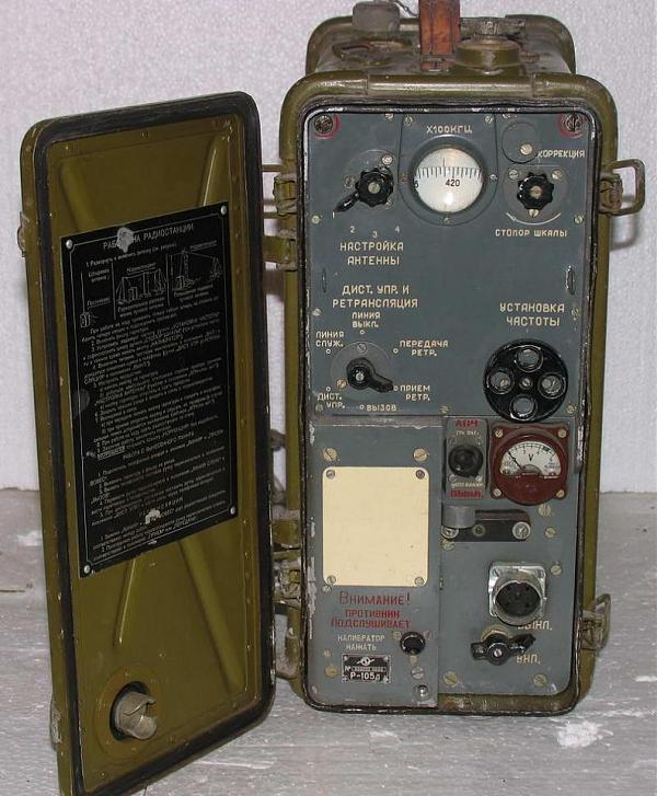 Type: R-105D "Astra-3"
- Channels: 203
- Power: 1W
- Type of modulation: FM
- Antenna: Rod, beam.
- Communication range: Up to 25 km
Type: R-108D "Astra-2"
- Channels: 171
- Power: 1W
- Type of modulation: FM
- Antenna: Rod, beam.
- Communication range: Up to 25 km
Type: R-109D “Astra-1”
- air defense.
- Frequency range: 21.5-28.5MHz
- Channels: 141
- Power: 1W
- Type of modulation: FM
- Antenna: Rod, beam.
- Communication range: Up to 25 km
Type: R-114D "Astra"
- Purpose: Radio station of battalion networks.
- Frequency Range: 20.0-26.0MHz
- Channels: ?
- Power: 1W
- Type of modulation: FM
- Antenna: Rod, beam.
- Communication range: Up to 25 km
Radio station R-105M/R-108M/R-109M “Sail”.

Production started in 1967 upgraded versions with improved characteristics and lighter weight R-105M/R-108M/R-109M Parus.
In 1956-1960. employees of the design bureau of the Voronezh plant "Elektrosignal" developed these portable tube radio stations. Chief designer of radio stations - Petrov K.Ya. Production - 1967-1986. The number of channels in the modernized radio stations of the Parus series was doubled, reducing the inter-channel distance to 25 kHz, which made it possible to increase the selectivity of the receiving path and reduce the out-of-band emissions of the transmitting path. There is no functional analogue of the R-114D radio station in this series, since already in 1962 the army began operating the R-107 “Binom” radio station, which with a margin covers the frequency range of all four radio stations of the “D” series.
But despite the emergence of a more versatile radio station, the R-105M “Parus-3” model turned out to be successful and appropriate, and the “indestructibility” was so high that the use of the radio station continued for a long time, in various structures of the Armed Forces and Civil Defense.
R105M1
Type: R-105M “Sail-3”
- Purpose: Radio station of battalion networks of motorized rifle and tank troops.
- Frequency Range: 36.0-46.1MHz
- Channels: 405
- Power: 1W
- Type of modulation: FM
- Antenna: Rod, beam.
- Communication range: Up to 25 km
Type: R-108M “Sail-2”
- Purpose: Radio station of battalion artillery networks.
- Frequency Range: 28.0-36.5MHz
- Channels: 381
- Power: 1W
- Type of modulation: FM
- Antenna: Rod, beam.
- Communication range: Up to 25 km
Type: R-109M “Sail-1”

Radio station R-126.
Since the beginning of the 60s, the production of this portable radio station of company radio networks, telephone, with frequency modulation, operating in the ultra-short-wave range, the smallest of the tube radios with a normal, superheterodyne, receiver, has been started.

Radio R-107 "Binom"
Since 1962, a VHF radio station of the R-107 “Binom” battalion radio networks has been produced. It works in simplex mode, frequency modulation, assembled according to a transceiver circuit.
The operating frequency range of the radio station is divided into two sub-bands: 20 - 36 MHz and 36 - 52 MHz. The radio has no squelch.
This VHF radio station implemented a wide-band frequency overlap, which made it possible to use it in all branches of the military, where niche radio stations of the Astra and Parus series were used.
Type: R-107 "Binom"
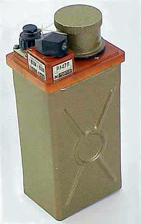
The second generation of wearable radio stations in the VHF band
Radio R-147 “Action-P”
Portable small-sized knapsack VHF FM radio receiver of the meter range.
Designed to provide communication:
- CB in the MSO-MSV link
- Air defense SV in MANPADS 9K34 "Strela-3"
- engineering troops - IRM engineering reconnaissance vehicle
There are 26 series with different combinations of channel frequencies. Designed to provide communication in the MSO-MSV link. The knapsack radio was worn on a strap over the shoulder, the earpiece was fastened with a rubber band around the head, the antenna was made in the form of spring strips and was attached to the earpiece with a clip. It was put into operation in 1971. The R-147P radio receiver is compatible with the radio networks of the R-147 radio stations.
Type: R-147P "Action-P"

Radio R-147 “Action”
Portable small-sized knapsack simplex VHF FM radio station of the meter range, with frequency modulation and the possibility of tone calling the correspondent. There are 26 series with different combinations of channel frequencies.
Designed to provide non-search and non-tuning communication in the lower levels of management.
Starting from the second generation, a radio communication distribution scheme was formed in the TZU, and in particular, the R-147 was the first radio station intended for the lower level - the platoon level.
Type: R-147 “Action”

Radio R-148 “Kid”
It was put into operation in 1971. Knapsack, for company radio networks, portable, VHF band, transceiver, telephone with frequency modulation (FM) and the possibility of tone calling a correspondent.
Type: R-148 “Baby”
- Purpose: Radio station of company networks.
- Frequency Range: 37.0-51.95MHz
- Channels: ?
- Power: 0.5W
- Type of modulation: FM
- Antenna: Pin.
- Communication range: Up to 6 km
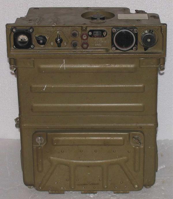 Radio R-107M “Binom-M”
Portable, knapsack radio station HF-VHF range, designed for battalion TZU networks. Works in simplex mode, frequency modulation. The R-107M radio station is assembled according to a transceiver circuit with one frequency conversion. The frequency setting is carried out by two controls - a switch on the top panel (1 MHz step) and a vernier on the front panel (smoothly).
The radio has no squelch. The radio station has an automatic antenna matching device. A characteristic feature of the radio station is the presence of an electronic digital frequency meter with an original display unit, implemented on miniature incandescent lamps.
Type: R-107M "Binom-M"
- Purpose: Radio station of battalion networks
- Frequency Range: 20.0-52.0MHz
- Channels: ?
- Power: 5W
- Type of modulation: FM
- Antenna: Rod, beam.
- Communication range: Up to 25 km
The third generation of wearable radio stations in the VHF band
Radio R-157
 Portable, VHF, simplex radio station, with frequency modulation, is designed to provide telephone communications in the platoon level of the TZU.
The kit consists of a transceiver in a case, a headset, a power supply, an antenna, straps, spare, accessories and documentation.
- Purpose: Radio station of platoon networks.
- Frequency Range: 44.0-54.0MHz
- Channels: ?
- Power: 0.5W
- Type of modulation: FM
- Antenna: Pin.
- Communication range: Up to 1.5 km
Radio R-158 “Viscount”
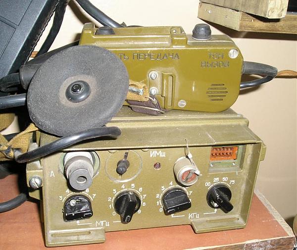 Portable, semiconductor, simplex VHF FM radio station for company units of TZU. Designed for radio communication with the same type of radio stations on the spot and on the move, when carried by a radio operator, on the move and in the parking lot, when installed on a car.
Type: R-158 “Viscount”
- Purpose: Radio station of company networks.
- Channels: ?
- Power: 1W
- Type of modulation: FM
- Antenna: Pin.
- Communication range: Up to 6 km
Radio R-159/M “Mikron/-M”
Knapsack VHF radio station for battalion level TZU, simplex with narrowband telegraphy and tone call, as well as with the possibility of remote control in telephone mode. Setting the frequency of the radio station using the switches and automatically tuning the transmitter to the antenna provide entry into communication within 20-30 seconds. Entry into radio communication is made without searching, and communication is carried out without tuning, at any frequency in the range. The radio station has a frequency range from 30 to 75.999 MHz and allows you to set the frequency in 1 kHz steps using the “MHz” and “kHz” switches. When installed on a car, they were supplied complete with a low-frequency amplifier.
 Type: R-159/M “Mikron/-M”
- Purpose: Radio station of battalion networks
- Frequency Range: 30.0-80.0MHz
- Channels: ?
- Power: 5W
- Type of modulation: FM/CH
- Antenna: Rod, beam.
- Communication range: Up to 25 km
Since portable VHF radios are designed to provide communication over relatively short distances, they widely use the meter wave range. Most radio stations operate in the 20 to 90 MHz band, which has certain advantages over other bands. The conditions for the propagation of radio waves in this area do not depend on the state of the ionosphere, time of day and year. Here, the level of station interference is much lower, since meter-range radio waves propagate along the earth's surface at distances limited by the line of sight between the receiving and transmitting antennas.
Structurally wearable radios are a single package that houses the transceiver and power source. All major organs are located on the front panel. A set of used antennas allow radio communication on the spot and on the move. Portable radio stations can be installed on various mobile objects.
All modern VHF, portable radio stations are carried out according to the transceiver scheme. They assume the use of the same stages and circuit elements, both in the transmitter and in the receiver. The use of joint circuits makes it possible to reduce the dimensions and weight of the VHF radio station, reduce the energy consumed from power sources, and simplify the process of setting up and operating the radio station. However, in this case, such radio stations are only simplex. Over time, there has been a trend towards expanding the frequency range of wearable radios.
Note: For more information on these radios, please visit the website.Military radio communications .
To be continued…
| Views total 10,774, today 1 |
Updated on 09/08/2017 14:15:11 Article sent by Alexander Tolstov aka ak108u |
P-100 - P-999 Wire communication equipment
P-100 - P-999
Wire communication equipment
R-100 - R-199 Radio communication equipment for the ground forces, as well as for general use.
R-100 - R-199
Radio communication equipment of the ground forces, as well as general-arms purposes.
- R-106 - RBS (Plakhpet)
- R-123/M - Magnolia (series of products of the 2nd generation)
- R-140 - Bereza / Stripe-N
- R-143 - Ledum
- R-154 - Amur
- R-154-2 - Molybdenum
- R-155/A/MR/N/R/U - Cowberry
- R-155P - Rowan?
- R-160 - Pine
- R-160P - Flash
- R-161 - Equator
- R-163 - Crossbow (series of products of the 4th generation)
- R-168 - Aqueduct (5th generation product series)
- R-170V - Artek-Sirius
- R-170P - Artek-Helios
- R-173 - Paragraph (a series of products of the 3rd generation)
Radio stations "R-105D", "R-108D", "R-109D"
Portable VHF-FM radio stations "R-105D", "R-108D" and "R-109D" have been produced since 1957.
Radio station "R-105D" type, code name "Astra-3", backpack, wearable, ultra-shortwave, telephone, frequency modulation, transceiver, with remote control and the possibility of relaying signals from other radio stations. Designed for non-search and non-tuning communication in radio networks or car radio nodes. Radio stations of the R-108D and R-109D types (Astra-2, Astra-1) have the same design, wiring diagram, parameters and differ in the range of operating frequencies.
- "R-105D" - 36.0 ... 46.1 MHz. There are 203 operating frequencies in the range.
- "R-108D" - 28.0 ... 36.5 MHz. There are 171 operating frequencies in the range.
- "R-109D" - 21.5 ... 28.5 MHz. There are 141 operating frequencies in the range.
Technical characteristics of the radio station "R-105D".
- Frequency range: Transmission 36.0...46.1 MHz. Reception 36.0...46.1 MHz.
- Frequency step: smooth tuning on a scale through 50 kHz.
- Frequency display: optical scale.
- Type of radiation: FM.
- Operating temperature range -40 +50 °С.
- Antenna connector for the antenna "Kulikov" bayonet.
- Antenna resistance 1...2000 Ohm.
- Power source two batteries 2NKN-24 or 2KN-32. Supply voltage 4.8 V (2x2.4 V).
- Operating time with the battery (reception/transmission 3:1) 12 hours with the KN14 battery and 17.5 hours with the 2NKP-20 battery.
Transmitter:
- Type: smooth local oscillator (LC generator).
- Output power not less than 1 W.
- Maximum frequency deviation ±7 kHz.
Receiver:
- Type: single conversion superheterodyne.
- Sensitivity is not worse than 1.5 μV with a signal-to-noise ratio of 10:1.
The radio station has the following types of antenna devices:
- flexible whip antenna 1.5 m high (with or without a counterweight of 3 beams);
- combined antenna consisting of a flexible whip antenna and 6 elbows (total antenna height 2.7 m), using a counterweight of 5 beams for parking operation;
- on-board antenna consisting of a combined whip antenna, a special bracket with a shock absorber for mounting the antenna on board the car and a connecting conductor 1 meter long, for operation while the car is moving;
- directional beam antenna 40 m long, suspended at a height of 1 meter above the ground for work at increased distances and from shelters;
- elevated antenna, consisting of a beam antenna 40 m long, raised at the radio station to a height of 5 ... 6 m, with a gradually decreasing opposite end directed at the correspondent, for working at increased ranges and from shelters.
With a combination of different antennas, reliable communication between two radio stations of the same type is possible at a distance of up to 10 kilometers when using simple antennas and up to 35...40 kilometers when using complex antennas.
Radio stations "R-105M", "R-108M", "R-109M"

Portable VHF-FM radio stations "R-105M", "R-108M", "R-109M" ("Parus-3", "Parus-2", "Parus-1") produced since 1967.
Portable knapsack VHF-FM radio stations "R-105M" replaced obsolete radio stations. The upgraded radio stations were also produced in 3 versions: "R-105M", "R-108M" and "R-109M" and differed from each other in various frequency ranges, coinciding with the old versions of radio stations "" R -105D "", but having more working channels in each band.
Frequency range:
- radio stations ""R-109M"" - 21.5 ... 28.5 MHz (13.95 ... 10.52 m),
- radio stations ""R-108M"" - 28.0 ... 36.5 MHz (10.7 ... 8.22 m),
- radio stations ""R-105M"" - 36 ... 46.1 MHz (8.3 ... 6.5 m).
Radio station of the "R-105M" type, receiving and transmitting, with the possibility of remote control and relaying of signals. All radio stations are equipped with whip antennas, short and long, as well as a directional beam antenna. Radio stations allow communication when they are located on the ground, behind the back of a walking radio operator, as well as on board a car when moving, from a shelter underground, using a coaxial feeder 10 m long. Radio stations provide a communication range of up to 30 kilometers with high efficiency and noise immunity. The DEMSh-1 microphone and TA-56m headphones are combined into a headset. You can also use a headset in the form of a handset. The radio stations are powered by 2x 2KNP-20 batteries or 4x KN-14 cells with a total voltage of 4.8 V. Frequency modulation, simplex communication. Sensitivity 1.5 μV. Optical scale with divisions of 25 kHz. Transmitter output power 1 W. Deviation 5 kHz.
Literature:
- Operating instructions for radio stations "R-105M", "R-108M", "R-109M".
Radio station "R-104" (RDS)

Army portable shortwave simplex radio station "R-104" (RDS) has been produced since 1949.
Has been in service since 1949. Produced stationary, transportable and wearable options.
The radio station "R-104" is designed for simplex shortwave communication in the frequency range from 1.5 to 3.75 MHz in two subbands. It is assembled according to the transceiver scheme. The receiving path includes one UHF stage, a mixer for the telephone mode, a mixer for the telegraph mode with a quartz filter, a two-stage IF amplifier with filters, and a low-frequency amplifier used as a modulating signal amplifier during transmission. The local oscillator is a tunable LC oscillator operating in the frequency range of 2.19-3.57 MHz. When operating on the first subband, the received signal is subtracted from the local oscillator signal to obtain an IF which is equal to 690 kHz, and when operating on the second subband, the local oscillator signal is subtracted from the received signal. When transmitting with a tunable local oscillator signal, a crystal oscillator signal with a frequency of 690 kHz is mixed. Amplitude modulation is carried out in the output stage of the transmitter, which uses the GU50 lamp (in the portable version of the radio station) or the 4P1L lamp (in the portable version). For coordination with different types of antennas, an antenna matching device is included in the radio set. The power supply of the radio station is made in the form of a separate unit. Frequency tuning is carried out on a visual circular mechanical scale. The power supply voltage of the radio station in the wearable version is 4.8 volt batteries. The mass of the radio station is 21.5 kg, the mass of the entire set is 39.5 kg. The output power on the antenna equivalent in the portable version is 20/10 W AM / CW, in the wearable version 3.5 / 1 W, respectively.
Radio station "R-104M" (Kedr)

Army portable shortwave simplex radio station "R-104M" (Kedr). Edition since 1955.
The R-104M radio station is distinguished by an extended range of 1.5 ... 4.75 MHz and minor changes in the electrical circuit.
Short-wave transceiver telephone-telegraph with amplitude modulation and mechanical half-duplex radio station of the R-104M type is intended for communication in the range of 1500 - 4250 kHz. The R-104M radio station is available in four versions: R-104AM3, R-104M, R-104UM and R-104UMU. The R-104AM3 and R-104M variants are automobile, the R-104UM variant is stationary (box), the R-104UMU variant is portable. Each of these options is designed to provide 2 types of work and transportation: - transportable, for full power operation and transportation by car; - wearable, for operation with reduced power and carrying by 2 radio operators. The transition from one type of operation of the radio station to another is carried out by changing the power sources, in which the transmitter power is simultaneously changed. A complete set of the R-104AM3 or R-104M radio station is placed and transported in a specially equipped vehicle of the UAZ-469 type and is adapted to work on the move and in the parking lot. In the car radio station R-104AM3, a VHF radio station R-105M with a power amplifier UM-3 is installed to provide communication on the go and in the parking lot of the car with the same type of radio station. The R-104M car version is not equipped with the R-105M and UM-3 radios, but the possibility of installing and operating VHF radios (R-105M, R-108M, R-109M) with the UM-3 power amplifier is provided. The radio stations R-104AM3 and R-104M provide for the possibility of recharging the batteries from the generator of the UAZ-469 car. The R-104UM radio station (stationary) is transported in 4 stowage boxes. The R-104UMU radio set is transported in one box. To operate the radio station in a wearable version, a transceiver and a power pack with batteries, antennas, etc. are used. different speeds movement and when carrying the radio station by the radio operator (walking, running or crawling). The radio station transfers without damage all types of transportation. The radio station remains fully operational in variable climatic conditions at temperatures from -40°С to +50°С and at relative air humidity up to 98%, at a temperature of +40°С.
The complete set of car radio R-104AM3 includes:
- R-104M transceiver.
- Power unit.
- Commander's console.
- Radio operator's bag.
- Rechargeable batteries type 6-ST-60-EM (6-ST-54-EM) -2 pcs. (of which one spare).
- Rechargeable batteries type 2KN-24 - 2 pcs. (spare).
- Bags with rigging equipment - 2 pcs.
- Matching fixture.
- Spare box.
- R-105M radio station with KN-14 batteries - 8 pieces (of which 4 pieces are spare) or 4 batteries 2KNP-20 (of which 2 pieces are spare).
- Power unit UM-3 with power supply unit BP-150.
- Spare property for the R-105M radio station.
- Spare property for power supply unit UM-3 and power supply unit BP-150.
The complete set of car radio R-104M includes:
- R-104M transceiver.
- Packing of food with accumulators 2KN-24 - 2 pieces,
- Ralist's bag.
- Power unit.
- Commander's console.
- Charging distribution box.
- Rechargeable batteries 6-ST-54-EM (6-ST-60-EM) - 2 pcs. (of which one spare).
- Rigging property.
- Spare box.
- Matching fixture.
- Connecting cables (set).
The complete set of the R-104UM box radio station includes:
- R-104M transceiver.
- Power pack with batteries 2KN-24 - 2 pcs.
- Power unit.
- Rechargeable batteries type 5KN-45K or 5KN-55 - 4 pcs. (of which 2 pieces are spare).
- Rechargeable batteries 2KN-24 - 6 pcs. (spare).
- Antenna stacking - 2 pcs.
- Matching fixture.
- Petrol-electric unit AB-1-P/30.
- Radio operator's bag.
- Spare box.
The complete set of portable radio station R-104UMU includes:
- R-104M transceiver. 2. Packing power supply with batteries 2KN-24-2 pcs.
- Radio operator's bag.
- Rechargeable batteries 2KN-24-4 pcs. (spare).
- Bag with antenna property.
- Spare box.
The full composition of the radio stations of the listed options is given in the form for the radio station.
The total weight of the complete set of the R-104AMZ radio station is 1870 kg (without service personnel).
The total weight of the complete set of the R-104M car radio is 1817 kg.
The wearable kit includes a transceiver and power pack. It is carried and serviced by two radio operators.
The total weight of the wearable kit is 39.5 kg, with the weight of the transceiver with case, cushion and carrying straps not exceeding 21.5 kg.
The total weight of the R-104M radio set in the box version (R-104UM) is 227 kg without stowage boxes (net) and 360 kg with boxes (gross).
Radio station "R-116" (Lily of the Valley)

The radio station "R-116" (Lily of the valley) has been produced since 1950.
"R-116" portable, army, knapsack, 10-channel, simplex VHF radio station in the range of 6.17 ... 5.85 m. The radio station is assembled according to a transceiver circuit. The receiver is assembled according to the direct amplification scheme and has 3 stages: UHF, super-regenerative detector, ULF. The functions of the amplifier of high-frequency and low-frequency signals are performed by the same 2Zh27P radio tube. When transmitted by appropriate switching, the super-regenerative detector stage is converted into a master oscillator. This cascade works on a 2Zh27P lamp. Amplitude modulation is performed in the output stage, assembled on a 2P29P lamp. The radio set includes a flexible whip antenna "Kulikov" 0.95 m high and a whip antenna 1.45 m high. The range of reliable two-way communication on a whip antenna 1.45 m high with the same type of radio station is up to 1 km The operability of the searchless and non-adjustable communication is preserved both when the radio stations are in the same temperature conditions within + 50 -40 ° C. The radio station is powered by a dry, combined anode-incandescent battery "BANSS-18M".
Main characteristics:
- Frequency range 48.65 - 51.35 MHz (10 channels, step 300 Hz).
- Modulation - AM.
- Frequency setting - 10 position switch.
- The sensitivity of the receiver is 6 μV.
- The output power of the transmitter is about 60 mW.
- Time of continuous work 12...18 hours (at a reception/transmission ratio 3:1).
- Radio station dimensions 310x325x170 mm;
- Weight 4.2 kg.
Literature:
- Description of the radio station "R-116" in the magazine Radio No. 11 for 1968.
R-200 - R-299 Broadcasting and special-purpose radio receivers, search airborne troops, reconnaissance stations.
R-200 - R-299
Broadcasting and special-purpose radio receivers, airborne search, reconnaissance stations.
- R-250/M/M2 - Kit/M/M2
- R-252 - Valley
- R-253 - VRP-3
Radio R-250 ("AS-1", "KIT")

"R-250/M/M2" ("R-670/M") is a legendary, beloved by many radio amateurs, shortwave, tube, trunk, desktop army radio receiver. Produced from 1948 to 1981 in several modifications: "R-250/M/M2" ("Kit/M/M2") - for ground forces; "R-670 / M" ("Mermaid / M") - for the troops of the navy. It was used for embedding in racks "KMPU/M" and "Crab/M". Differed in high sensitivity, excellent dynamics and stability of work. Number of lamps: 19. Developers of the receiver: Anton Antonovich Savelyev, Yuri Alexandrov (U1SX) and others. Initially, the design was called "AC-1", later in the modifications of the design, the number "1" was replaced by "2" and the receiver became known as "AC- 2" (according to the initials of the author). The radio received the Stalin Prize in 1950 [more... (in English)].
The extended range (1.5 - 33.5 MHz) in the R-250M/M2 radio receivers was dictated by the version of the order. There were several versions - with and without an extended range. A case with contours and additional straps was attached to the set of the radio receiver with an extended range. The R-250 receiver did not have an extended range at all. The "R-250M2" also had an order option with a 12-volt static DC converter, that is, the receiver could be powered by some kind of on-board network. The "R-250M" and "R-250M2" also had an order option with an auto-tuning motor. Inside, near the front panel, there was a small flat and round synchronous motor that remotely tuned the receiver in frequency. Element base: "R-250" - lamps with an octal base; "R-250M2" - finger lamps.
Photo 5 shows a photo of the GDR modification "R-250M" with a black front panel. That is, this is the same "R-250M", but with German inscriptions, except for some made in Russian.
The receiver has an accurate mirror optical photo tuning scale, a temperature-controlled quartz stabilizer for the local oscillator frequency. Number of subbands: 12, 2 MHz wide each. Range switch - mechanical, drum type. In the first subband "R-250" operates as a superheterodyne with one frequency conversion. In other subbands, it has the first tunable IF (1.5 - 3.5 MHz) and the second fixed (215 KHz). The main selection filter is the IF = 215 KHz filter with variable bandwidth. The bandwidth adjustment knob is placed on the front panel. The front panel also has volume and gain control knobs, input trim, antenna type switching, smooth and coarse tuning, subband switching and types of work. To monitor the status of various stages of the receiver on the front panel there is a measuring device with a controlled value switch. "P-250/M/M2" is a very large and very heavy device and takes up a lot of space on the table.
The power supply of the radio receiver is located in a separate housing. He transforms AC voltage network to the voltage required to power the filament and anode circuits of the receiver (+160 V anode voltage, at a current of 120 mA and ~ 6.3 V. glow, at a current of 8 A).
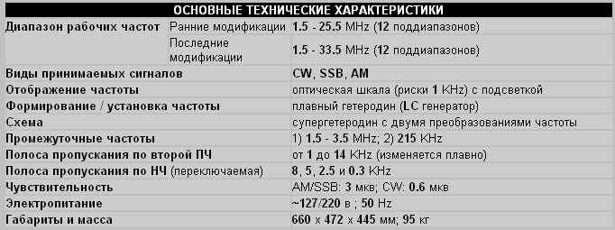
Literature:
- Schematic diagram of the R-250 radio receiver
R-300 - R-399 Equipment for radio reconnaissance, radio interference; direction finders.
R-300 to R-399
Equipment for radio intelligence, radio interference; direction finders.
- R-309 - Barley
- R-309A - Jump
- R-310 - Watch
- R-317 - Tape
- R-327 - Topol R-350 - Eagle
- R-353 - Proton
- R-354 - Bumblebee
- R-355 - Ryabina-M1
- R-376/M - Don/M
- R-399A - Katran
R-311 - Portable radio receiver
R-359 (Pelican) - DF radio receiver

R-359 (Pelican) - a shortwave, two-channel direction-finding radio receiver with a cathode ray tube (CRT) as an indicator, the "thunderstorm" of all radio hooligans in the 1970s and 1980s. Produced in both automotive and stationary versions. Assembled on baseless lamps. It has vertical and horizontal deflection channels. The signal from each antenna input is fed to its own channel, from the output of the channels the signal is fed to the vertical and horizontal plates of the cathode ray tube. The telegraph local oscillator is tuned within ±3 KHz. The attenuator can attenuate the signal by 10 times. Separate gain controls for IF and LF. The IF bandwidth switch has two positions WIDE and NARROW. There is an output for head phones. The receiver is made on subminiature rod radio tubes with a filament voltage of 1.2 V, with the exception of the input of each channel where 6Zh5B are installed. "R-359" has a projection-type photo scale, and there are 4 projection lamps. As they fail, they can be changed by turning a special knob. The handle of the goniometer is mechanically rigidly connected to the indicator scale. All receiver nodes are milled aluminum blocks closed with covers. On a common basis, they are assembled into a single structure and placed inside the receiver housing. "R-359" can be used both with special direction-finding antennas and with conventional antennas, like an ordinary communication radio receiver. In terms of reception quality, it resembles the "R-326" and takes bearings with very high accuracy.
The control room "R-359" (Pelican) is usually transported on two ZIL-157 vehicles. In one car there is a control room, consisting of two "R-359" (Pelican) "R-250M2" "R-105M". In the second car - masts, antennas, etc. Antenna economy consists of 8 whip antennas, and the second field of 4 crossed squares. This entire economy is served by a whole squad of fighters.

The so-called light version of the R-359 (Pelican) is also known. It is called "Eagle-1". Consists of "R-359" (Pelican) "R-105M" and antennas in the form of two frames in the form of a torus, crossed at 90°C. This control room has "Eagle-1" nameplates on all components. This is all mounted on the GAZ-69. Powered by car batteries or mains alternating current.
- Operating frequency range 1.5 - 25 MHz
- Number of subranges - 8
- Operating modes AM, CW
R-375 (Kaira) - Radio receiver
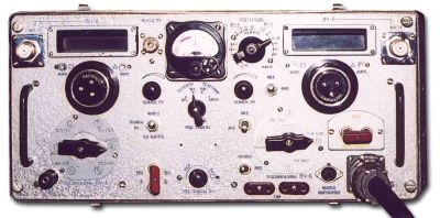
"R-375" (Kaira) - army VHF (MV / DMV) radio receiver. On the front panel, on the left, there is a two-speed vernier device with a photoscale for the 20-210 MHz MV band, and the same UHF 210-500 MHz band on the right. Two antenna inputs - MV and UHF. There is a 4 MHz IF output, a broadband (up to 400 KHz) low-frequency output and an output to the TLF 0.3-2.5 KHz.
The radio receiver is made on 34 lamps.
The mains power supply is stabilized, with 4 lamps. The tubes in the receiver have been selected for optimum use in the specific stages. In the input part of the meter range, 6S3P and two 6S4P lamps were used, and in the input part of the decimeter range, 6 pieces of ceramic-metal 6S17K and one 12S3S. The rest of the tract is made on 6Zh1P 24 pcs. This solution made it possible to achieve very high sensitivity in the VHF range, for receivers of those years. The mains power supply has a stabilizer for the anode-screen voltage and lamp incandescence. Used lamps 6S19P - 2 pcs., 6N3P - 2 pcs., SG15P.
Since the minimum possible bandwidth of the path is 40 KHz, reception at frequencies below 29 MHz is practically impossible, several stations fall into the receive channel at once. But at frequencies of 29 - 500 MHz, it is quite possible to use the receiver and you can do amateur radio reconnaissance. The 4 MHz IF output can be connected to a panoramic indicator and the spectrum of amateur radio stations operating on the two-meter band can be observed on the screen. The broadband bass output can be used to record music programs on a tape recorder.
MAIN SPECIFICATIONS
- Frequency range 20 - 500 MHz
- Modulation (operating modes) AM, FM, TLG-beat and TLG-tone
- Sensitivity in the narrow band mode (40 KHz) is not worse than 1.5 μV
- Sensitivity in wide band mode (200/350/600 KHz) 4-7.5 µV.
- The power consumed from the network is 180 watts.
- The mass of the radio receiver is 20.3 kg.
- power supply 17.5 kg.
The receiver has 8 subbands:
- 20-31.5 MHz
- 31.5-50 MHz
- 50-79.5 MHz
- 79.5-115.5 MHz
- 115.5-161 MHz
- 161-210 MHz
- 210-354 MHz
- 354-500 MHz
On subbands 1 and 2, the receiver operates with 1IF = 4 MHz, from 3 to 6 subband 1IF = 30 MHz 2IF = 4 MHz, on subbands 7 and 8 1IF = 72 MHz, 2IF = 4 MHz.
Literature:
Radio receiver "R-309"

The main professional communication radio receiver "R-309" (Barley) has been produced by the Kharkov Radio Plant named after the 25th Congress of the CPSU since 1967
A superheterodyne with double frequency conversion, assembled on rod-type lamps with flexible leads for soldering into the circuit: 11 lamps 1Zh29B, 2 - 1Zh37B, 12 - 1Zh24B, a total of 25 radio tubes. Receiver weight - 33 kg, power supply - 14 kg. UHF two-stage on lamps 1Zh29B. The cascades are made according to the transformer scheme. There are two first local oscillators: a local oscillator of 1-4 subbands and a local oscillator of 5-8 subbands (1ZH29B). All local oscillators are non-switchable. The frequency multiplier is assembled on 2 lamps 1Zh29B. The first mixer 1Zh37B. The receiver has 8 subbands and each has its own intermediate frequency: 305, 610, 1220, 2040, 8585, 2585, 3515, 9515 kHz. The amplifier of the first IF is two-stage, the mixer stage and the amplifier stage on a 1Zh29B lamp. The second converter converts the first IF to the second, 465 kHz. The second local oscillator is quartzized (1Zh24B). Frequencies 770, 1075, 1685 and 1975 kHz. On the 5th and 8th sub-bands - 90-50 kHz, on the 6th and 7th sub-bands 30-50 kHz. The 2nd IF amplifier consists of 5 amplification stages.
Has two channels for narrow and wide bandwidth. The first and second stages of the narrow band are made according to the scheme of quartz filters, allowing you to change the band from 200 Hz to 4 kHz. (1ZH24B). The 4th cascade of the UPCH is assembled on a 1Zh29B lamp. Detector on 1Zh24B. Two-stage ULF, on a 1Zh24B lamp, assembled according to a rheostat circuit and an end stage on 1Zh29B. The 3rd local oscillator is smooth, on a 1Zh29B lamp. The 3rd converter for telegraph reception using the beat method, assembled on a 1Zh37B lamp. Quartz calibrator (1 MHz) on a 1Zh29B lamp. The sensitivity of the radio receiver to the antenna equivalent of 100 Ohm with a signal-to-noise ratio of 3: 1 and an output voltage of 1.5 V at the load, in a wide band of 4 kHz, in telephone mode is not worse than 3 μV, in telegraph mode, not worse than 0.6 μV. Attenuation of sensitivity in the mirror channel is at least 4 thousand times, on 6-7 subbands at least 2 thousand times. According to IF signals - 10 thousand times. The uneven frequency response for the output to telephones in the range from 300 Hz to 3000 Hz is not more than + 2 dB and -6 dB from the average frequency of 1000 Hz. The number of affected reception points is 20. There is a 0.5 V low-frequency output, AGC for dual reception. There is an electric motor for AFC. The R-309 radio receiver works with the R-319 panoramic analyzer. The optical scale is graduated directly in kHz, easy to read, but in the upper ranges due to frequency multiplication is too compressed. Due to the lamps used and their modes of operation, the receiver is quite noisy. The range of received frequencies is divided into eight sub-bands: 1 - 36 MHz. Range switch: mechanical, drum type. Receiver dimensions: 480x290x440 mm. Powered by AC 127 or 220 volts, through an external power supply unit or from a 12 volt battery.
Radio receiver "R-312" (Beta)

Special military VHF radio "R-312" (Beta). Release since 1954.
The radio receiver "R-312" was intended for the organization of radio communications and radio monitoring in the Soviet Army. The radio receiver is assembled on ten radio tubes of the 2Zh27L type and operates in five sub-bands with a smooth overlap of frequencies from 15 to 60 MHz, with sufficient margins at the edges of the sub-bands. The receiver can receive radio stations operating with AM, FM and tone modulation, as well as telegraph and suppressed carrier signals. When receiving AM-FM radio stations, the sensitivity of the receiver is 5-8 microvolts, and when receiving telegraph and SSB - 2-3 microvolts. The radio has a two-stage IF bandwidth control that switches automatically when modulation is selected. When receiving AM signals, the IF bandwidth can be changed from 9 kHz with a narrow band, up to 25 kHz with a wide band, when receiving FM signals from 60 and up to 180 kHz, respectively, when receiving telegraph signals and SSB from 3 to 9 kHz. With a strong signal, signal bursts outside the 3 kHz band are very noticeable. The receiver has a mode for receiving telegraph signals using the method of beating between audio frequencies, the so-called tone modulation. Selectivity in the adjacent channel at the receiver is 74 dB, and this is the maximum value when receiving CW - SSB, in the mirror from 36 to 60 dB. The IF is 3 MHz.
The receiver is powered by 2.5 V batteries, which feed the glow of the lamps directly, and the anodes of the lamps are fed through a vibration transducer with an output voltage of 80 volts. The current consumption for the anode is not more than 25 mA, for the incandescence 0.7 A. The power of the low frequency amplifier is 50 mW. The dimensions of the receiver are 445x290x255 mm, its weight is 20 kg.
The receiver was considered secret until 1965, and was produced until October 1971.
Radio receiver "R-323" (Digital)

Army HF-VHF radio "R-323" (Figure). Model 1961.
Army, tube HF-VHF radio "R-323" is designed to receive signals with amplitude, frequency modulation and telegraph. The receiver is assembled according to the superheterodyne circuit with 3 conversions on 28 lamps (5 lamps 1Zh29B and 23 lamps 1Zh24B) and six semiconductor diodes D2G. The maximum number of simultaneously operating lamps, depending on the type of operation of the receiver, is 17. The receiver is placed in an aluminum alloy casing. The design of the receiver provides water tightness. When immersed in water to a depth of 0.5 m for up to 30 minutes, the penetration of water inside is excluded. For power supply from AC 220 or 127 V, the receiver is equipped with a separate remote stabilized rectifier "VS-2.5M". By appearance the device is similar to the "R-326" receiver, the difference is only in the range of received frequencies.
Main technical characteristics:
- Receiving frequency range: 20...100 MHz (4 subbands)
- Types of received signals: AM, CW, FM.
- Frequency setting error: 10 KHz.
- Frequency display: optical scale (resolution 10 / 20 KHz).
- Sensitivity in AM (narrow / wide band): 3 / 5, FM - 2.5, CW 1 μV.
- Bandwidth (at level 0.5): 8, 25, 85 KHz.
- Intermediate frequencies 1 IF: 9 MHz; 2 IF: 2.86 MHz; 3 IF: 473 kHz.
- LF output voltage on one pair of low-resistance telephones: 4.5 V.
- Supply voltage: +2.5 V.
- Operating temperature range: -50 +50°C.
- Dimensions: 255 x 270 x 370 mm.
Radio receiver "R-323M" (Tsifra-M)

Army tube HF-VHF radio "R-323M" (Tsifra-M). Release since 1978.
"" R-323M "" - an army tube HF-VHF radio. Designed to receive telegraph signals and signals with amplitude and frequency modulation. The radio receiver "R-323M" is assembled according to the superheterodyne scheme, with two frequency conversions. Has 4 subranges. Frequency indication is carried out using LED indicators. Bandwidth - switchable, has three positions. The receiver has no gain control. The input has a step attenuator with attenuation of 0, 20 and 40 dB. In appearance, this radio receiver is practically similar to the radio receiver of the "R-326M" type, all its difference is only in the range of received frequencies.
Main technical characteristics:
- Receiving frequency range: 20 - 100 MHz.
- Frequency shaping/setting: smooth local oscillator (LC oscillator).
- Frequency display digital meter, resolution: 1 KHz.
- Sensitivity in AM mode (narrow / wide band): 3/5 µV, FM 2.5 µV, CW 1 µV.
- Attenuation in the mirror channel is not less than: 800 times.
- Receiver circuit: superheterodyne with two frequency conversions.
- THD: 10%.
- Rated supply voltage: +12 V.
- Overall dimensions (with protruding parts): 255 x 270 x 370 mm.
Radio receiver "R-326". Rustle

Radio receiver "R-326". Rustle. Production started in 1963
""R-326"" Rustle - tube, superheterodyne, shortwave, army radio. The front panel of the receiver is closed with a cover. It has 6 subranges.
The bandwidth is adjustable. The rectifier VS-2.5M is used for power supply from the mains. In appearance, the model is similar to the receiver - the difference is in the frequency range.
Technical characteristics of the radio receiver "R-326":
- Operating frequency range: 1-20 MHz (6 subranges).
- Types of received signals: AM, CW (adjustable local oscillator).
- Frequency display: optical scale.
- Frequency shaping/setting: smooth local oscillator (LC oscillator).
- Power supply: ~220 V; 50 Hz.
- Overall dimensions: 235 x 295 x 395 mm.
- Weight..... 20 kg.
Radio receiver "R-326M"

"R-326M" - army, shortwave AM/CW/SSB radio. The disadvantage is that there is no amplification for HF. In appearance, this radio is very similar to a radio, the difference is only in the range of received frequencies.
Peculiarities:
- Element base: transistors and microcircuits
- Input circuits: on "field workers";
- Receiver circuit: superheterodyne with double frequency conversion;
- GPA: similar to "Drozdiver", with divisors by subranges;
- 4 shifts bandwidth, (switchable EMF) 0.4; 0.8; 2.7; 5.4 kHz at 6 dB;
- Input attenuator (three positions): 0, 20, 40 dB;
- Dynamics: around 70 dB;
- SLR attenuation: 70 dB;
- The first IF for 1-3 sub. - 710 KHz, for 4-7 subs. - 2.8 MHz, second IF - 500 KHz;
- There are outputs of the first and second IF and telegraph local oscillator on the front panel;
- 1st IF attenuation: 80 dB.
- Receiving frequency range 1.5-32 MHz (7 subbands)
- Types of received signals AM, CW, SSB
- Frequency display on LEDs (resolution 1 KHz)
- Sensitivity 0.8 uV (CW, SSB); 4 microvolts (AM)
- Food From the accumulator +12 in; KNP-3.5A (10 pcs.)
- From the on-board network +27 V (through the PK-12 converter)
- From AC ~ 220 V; 50 Hz (via VS-12 mains power supply)
- Power consumption from battery 10 and 5 W (when the scale is on and off)
- Overall dimensions and weight 235 x 295 x 395 mm; 20 kg
Literature:
- Schematic diagram of the R-326M receiver
Radio station "R-392" ("R-392A")

Army VHF-FM radio station "R-392 / A" since 1982 was produced by the Orsha plant "Red October".
Radio R-392 "Sokol" (R-392A "Sokol-M" ) is intended for simplex radio communication at 6 fixed frequencies in the range of 44 ... 50 MHz. The radio station has speech coding by inversion, noise suppressor. With the same type of station on a standard antenna, in open areas, confident radio communication is possible at a distance of 7 ... 10 kilometers. A regular battery 10-NKGTS-1D gives the radio station continuous operation for 10 hours for reception or one hour for transmission. The duration of the transmission should not exceed 5 minutes. The receiving part of the radio station "R-392 / A" is assembled according to a superheterodyne circuit, with double conversion. The first IF of the radio station is 13 MHz, the second is 1.6 MHz. The sensitivity of the radio station is 0.5 μV. The output power of the transmitter is not less than 1.5 W. Frequency modulation, with a deviation of 5 ... 10 kHz. The radio station is powered by a standard battery or other source, with a voltage of 12.6 volts. The receiver in noise canceling mode consumes 40 mA. The transmitter consumes up to 500 mA. Operating temperature range from -50 to +50°C. The dimensions of the radio station are 145x60x235 mm, the weight of the set is 3.3 kg. A radio station with the "A" index operates on other frequencies in the same range.
Literature:
- Wiring diagrams
R-400 - R-499 Radio relay stations, satellite and tropospheric communication stations, radio receiving units.
R-400 - R-499
Radio relay stations, satellite and tropospheric communication stations, radio receiving nodes.
- R-438 - Barrier-T
- R-441U - Liven-U
R-500 - R-599 ???
R-500 to R-599
???
R-600 - R-699 Radio communication equipment of the Navy.
R-600 - R-699
Radio communication equipment of the Navy.
- R-603 - Quark
- R-609 - Acacia
- R-619 - Graphite
- R-625 - Fir
- R-631 - Flame
- R-654 - Perch
- R-670/M - Rusalka/M
- R-671 - Hop
- R-672 - Fog / 2GLK
- R-673 - Melnik / PRV
- R-675 - Onyx
- R-680 - Cycloid
- R-697 - Guys
R-700 - R-799 Analyzing and indicating devices, digital radio communication equipment, Air Force radio receivers, special. Navy complexes.
R-700 - R-799
Analyzing and indicator devices, digital radio communication equipment, Air Force radio receivers, special equipment. Navy complexes.
R-800 - R-899 Radio communication equipment of the Air Force.
R-800 - R-899
Radio communication equipment of the Air Force.
- R-800 - RSIU-3M
- R-801 - RSIU-4 R-801P - RSIU-4P
- R-805 - RSB-5
- R-807 - RSB-70 / Berkut / Danube
- R-814 - RAS-VHF
- R-824 - RAS-VHF M1
- R-836 - Irtysh
- R-836UM - Helium
- R-838 - Viola-A
- R-838K - Kremnica-A
- R-838KN - Kremnica-N
- R-838KTs - Viola-Ts
- R-842 - Atlas
- R-848 - Mars
- R-855U/UM/-2M - Komar
- R-860 - Feather
- R-861 - Anemone
Aviation search and rescue radio station "R-855"

Aviation search and rescue radio station "R-855" has been produced since 1959.
The radio station "R-855" (Komar) is designed for radio communication in extreme conditions. It was used in aviation, for communication between paratroopers and the ground, in emergency and search situations. The radio station "R-855" completed the suits of military pilots. When used in emergency cases, when falling on the water, the kit, in which the antenna was inflatable, was inflated with compressed air and the radio station began to give the “SOS” signal. Subsequently, the radio station was modernized several times into "R-855-2M", "R-855U", "R-855UM" and other options. The first radio stations were assembled on rod lamps, subsequent ones on transistors. In addition to the model, the radio stations also had configuration options A, B, C. A headset could be connected to the radio station. The operating frequency of the radio station is 121.5 MHz. Transmitter power 100 MW. Sensitivity 5 µV. The detection range of signals from a height of 10,000 meters reached 300 km.
Radio station "R-809M"

The R-809M radio station has been produced presumably since 1972.
""R-809M"" is a stationary portable VHF radio station used mainly in aviation. It works in simplex mode with AM. The frequency range of reception and transmission is 100 ... 150 MHz. The frequency is discrete in arbitrary units. The reception sensitivity is 5 μV. Transmitter output power 5...7 W. Battery powered 11...14 volts. Current consumption for transmission 2 amperes, for reception 300 mA. The radio station has a minimum of control knobs.
R-900 - R-999 Radio complexes, mobile radio units.
R-900 - R-999
Radio complexes, mobile radio units.
- R-974 - Alphabet
Radio receiver "Krot-M"

The radio receiver "Krot-M" has been produced since 1953 at the Kharkov Radio Plant No. 158 (p \ box 165).
The Krot-M radio receiver is a slightly modernized version of the receiver. Outwardly, it is distinguishable from its predecessor by the gray-blue color of the front panel. The position of the wiring harnesses and the UHF layout has been changed. The contacts of the drum leads and current collectors without gold wire are replaced with contact pads made of silver-cadmium composite.
Specifications:
- Receiving frequency range: 1.5 - 24 MHz
- Sensitivity: 0.25 uV CW, 3 uV AM
- Working hours: CW, AM
- Bandwidth: 1 kHz, 3 kHz and 10 kHz
- Image attenuation: >50dB
- Adjacent channel attenuation: : >50dB
- Frequency stability: 1.5 kHz/hour
- Dimensions: 681 x 356 x 478 mm
- Weight: receiver 85 kg, power supply 40 kg
Radio receiver "Volna-K"

Stationary superheterodyne tube radio "Wave"Designed for auditory reception of telegraph (continuous and tonal) and telephone signals. In addition, the radio receiver can be used in a set of equipment for direct-printing facsimile reception.
Receivers" Wave"Produced at the Aleksandrovsky Radio Plant of the Vladimir Region in the USSR and the Petropavlovsk Radio Plant named after S. M. Kirov (since 1959). The start of production was the end of the 1950s. The receiver was produced until 1985. It was planned as a communication MF / HF sea and river ship civilian receiver, however, he had a very significant drawback in this capacity - the contours were upset from shock loads in the drum. The receiver was generally unreliable as a communicator and switched to the role of an auxiliary, and then a broadcaster, instead of a receiver " Lyubava". For amateur purposes, it is valuable as an IF on the range 2 MHz, as it has good optics there, and in the presence of a HF converter with quartz-band stabilization, it can provide very comfortable reception.
The radio receiver is made in the form of a desktop structure in a shielded metal case according to a superheterodyne circuit on fourteen finger lamps of the six-volt series with double frequency conversion. Double frequency conversion is used on bands 5 to 9 of the Volna-K receiver; on bands 6 to 9 - "Wave-K1", on bands 7 - 9 - "Wave-3", and a single conversion on the remaining bands. The use of double frequency conversion makes it possible to provide the necessary attenuation of interference in the image channel on HF bands, and also allows you to get a band on all bands 0.5 KHz, since in this case the bandwidth is provided by the choice of a relatively low second intermediate frequency ( 85 kHz). On long-wave bands, a high intermediate frequency is not needed and the necessary attenuation of mirror noise is achieved by a circuit with one transformation.
KEY FEATURES:
- There are six modifications of the radio: 1] " Wave-K"; 2] "Wave-CT" (tropical variant); 3] " Wave-K1"; 4] "Volna-K1T" (tropical variant); 5] " Wave-K2"(differs from "Volna-K" in that the body of the receiver is made of aluminum alloy); 6] " Wave-3".
- Element base- lamps (6K4P, 6A2P, 6Zh2P, 6P1P, 5Ts4S, 6N3P, SG3S, A6-3, MN-3) and semiconductors (D2Zh, D2E, D102).
- Range switch- mechanical, drum type. Number of subranges - nine.
- Frequency setting and tuning radio receiver is provided manually using a mechanical vernier. Vernier four-section KPE has four deceleration steps. Each stage consists of two gear wheels with a gear ratio 1: 3 . The design of the vernier is completely backlash-free due to the fact that the teeth of the driving wheels of each stage are wedged between the teeth of the two driven wheels.
- Scale- combined with mechanical and optical photo-display of the received frequency with light illumination.
- The receiver has step adjustment IF bandwidth.
- Input circuits radio receivers in the entire frequency range are designed to work from an open antenna of any length. The input circuits of the "Volna-3" receiver, in addition, are designed to turn on a symmetrical antenna through a two-wire feeder with a characteristic impedance 200 ohm. The receiver input is protected from radar interference, as well as from high RF voltages induced in the antenna from transmitters operating nearby.
- Exit The radio receiver is designed to connect:
- two pairs of low-impedance telephones (Volna-K);
- one pair of low-impedance telephones and a line with a load 600 ohm (Wave-K1);
- two pairs of low-impedance telephones and a line with a load 600 ohm, with the loudspeaker turned off (Wave-3).
- to the receiver mounted dynamic loudspeaker that provides listening to transmissions at an output power of the order 0.2 - 0.3 Tue. It is possible to turn off the loudspeaker with a toggle switch located on the front panel. In addition, the intermediate frequency voltage is output to the front panel of the Volna-3 receiver. 85 kHz.
- On the front of the radio located the following governing bodies:
- range switch knob;
- tuning knob;
- IF gain adjustment knob;
- strip switch knob;
- work type switch knob;
- TLG tone control knob;
- handle of electric scale corrector;
- switch knob "Lamp currents" (to control the currents of 10 lamps in the receiving path);
- bass gain control knob;
- toggle switch for turning on the receiver;
- toggle switch for switching on AGC (only for radio receivers "Volna-K", "Volna-K2", "Volna-3", "Volna-KT");
- loudspeaker toggle switch;
- toggle switch for broadcasting (only for radio receivers "Volna-K1", "Volna-K1T");
- toggle switch "Receiver", "Sound pickup" (only for radio receivers "Volna-K1", "Volna-K1T");
- toggle switch for switching reception to symmetrical and asymmetrical antennas (only for the Volna-Z radio receiver).
- Inside the radio receiver (on block N 1) a quartz switch is installed. It is possible to correct the exact scale according to the internal quartz calibrator with an electrocorrector.
- In addition to the main amplification path, the radio receiver has: quartz calibrator, III local oscillator, amplifier And AGC detector.
- Quartz calibrator allows you to provide the specified accuracy of the receiver calibration by periodically checking the optical scale on the calibration points.
- Third local oscillator necessary when receiving undamped oscillations, as well as during calibration.
- To turn on the quartz calibrator, as well as the third local oscillator, use the switch " Type of work" displayed on the front panel.
- The receiver has applied enhanced AGC.
- Rectifier mounted inside the radio. The rectifier provides power to all local oscillators with stabilized voltages +105 in and ~6.3 c, and all other cascades - unstabilized voltages +220 in and ~6.3 V.
- Provided the following options nutrition radio receiver:
- from AC voltage 220 , 127 , 110 in with frequency 50 Hz;
- from the DC voltage 220 , 110 And 24 c via converters (for the option of power supply from the DC mains, a remote converter switch is provided in the radio set. Types of converters, depending on the power supply option, are supplied separately).

COMPLETENESS:
- Set spare parts in a box (as part of the radio " Wave-K1" Excluded);
- Accompanying technical documentation;
- Two type converters OP-120 F1 110 IN);
- Two type converters OP-120 F2(for a radio receiver powered by a DC mains voltage 220 IN);
- Two type converters OP-120 F3(for a radio receiver powered by a DC mains voltage 24 IN);
- Converter switch (for a radio receiver powered by a DC mains voltage 220 , 110 , 24 IN);
- Headphones (as part of the radio " Wave-K1"are not included).
Radio receiver "KUB-4"

The KUB-4 battery radio receiver has been produced by the Kazitsky Leningrad plant since 1930.
The radio receiver "KUB-4" (developed by the Shortwave Shock Brigade, 4-tube) is a semi-professional radio receiver with direct amplification and is intended for operation at low-level radio stations and for receiving shortwave broadcasting stations. The receiver is powered by direct current sources. It has one high frequency amplification stage, a regenerative detector and two low frequency amplification stages. Subsequently, the plant produced several versions of this radio for use in the army and navy. The purpose of such receivers was determined by the letter after the number 4, for example, "KUB-4M" - a marine version. Variants of the RP were produced until 1940.
This shortwave receiver was considered one of the best in the USSR in the early 1930s: it was reliable, sensitive, and unpretentious.
KUB-4 was used wherever shortwave radio communication was required: on land and at sea (including submarines of the "Pike" type), and in the Arctic, and in the Red Army, and at club amateur radio stations (even in the post-war period) . He also met with individual shortwave radio amateurs, but, apparently, infrequently: in those days, for an ordinary Soviet amateur, an industrial communication receiver was an inaccessible luxury. Going to the North Pole in 1937, E. Krenkel left his own KUB-4 in Moscow as a reward to the one who establishes the first amateur radio contact with him, and then such a prize was, apparently, still very tempting.
The designation "KUB-4" could also be deciphered as "Short-wave, universal, battery, four-lamp". Although it used five lamps, only four were used directly in the signal path, and only such lamps were taken into account in the characteristics of the receivers. The design of V. Dobrozhansky (EU3AJ, then before the war - U1AB) was taken as a basis. By the way, in the 1970s, VL Dobrozhansky became one of the leading project managers of the first Soviet amateur radio satellites "RS".
Radio tubes and other components were quite bulky, so, despite the simplicity of the circuit, the dimensions of the device were comparable to, say, the dimensions of a UW3DI tube transceiver (only two times smaller in depth). Range switches in HF equipment were rarely used then, and for different ranges they used interchangeable inductors inserted into special connectors (often lamp sockets and plinths were used for this). At that time, tuning capacitors of variable capacitance were not yet combined into multi-section units with a common axis, therefore, when tuning along the range, each circuit had to be tuned to resonance with a separate knob with a vernier. This receiver had two such verniers.
Below is an excerpt from the book "Short Wave Technique" by Z. B. Ginzburg and I. P. Zherebtsov (Radio Publishing House, Moscow, 1938):
"KUB-4 is a very common industrial four-tube receiver with high-frequency amplification, a detector stage and two low-frequency amplification stages. Of these, the first stage is with transformer coupling, and the second stage is with resistances. The receiver covers the wave range from 12 to 200 m using a set of 5 pairs of coils.
Coil number 1 gives a wave range from 10 to 19 m
" № 2 " 19 " 34 "
" № 3 " 34 " 69 "
" № 4 " 69 " 112 "
" № 5 " 112 " 200 "
Each coil is wound on a frame resembling a lamp base in shape and having 4 plug legs at the bottom. The ends of the coil are brought out and soldered to these legs.
The antenna and grid coils of the first lamp are wound on a common frame. Also wound together are the anode coil of the first lamp and the feedback coil.
Schematic diagram of the radio receiver "KUB-4"
Feedback is controlled by changing the voltage applied to the anode of the detector lamp. These changes are carried out by a kind of potentiometer, composed of two arms: one - constant resistance (Kaminsky) and the second - variable - electronic lamp with grid and anode shorted to each other. When the incandescence of this lamp changes, the ratio of the arms of the potentiometer changes and thus the anode voltage of the detector lamp is adjusted.
The receiver box is metal. It is divided inside by transverse screens into three parts. The first contains the high frequency stage, the second contains the detector, and the third contains the low frequency amplifier. To adjust the contours, verniers are used, which give a very precise and smooth adjustment.
In the high-frequency cascade, the SB-112 or SB-147 lamp is used; as a detector - lamp UB-107 or UB-110. The first low-frequency cascade also works on a UB-107 or UB-110 lamp. In the terminal stage, UB-107, UB-110 or UB-132 lamps are used. To adjust the feedback - UB-107 or UB-110.
The receiver requires 120 volts for the anode, 40 volts for the shielding grid, 4 volts for the filament, and 2 volts for biasing the high and low frequency amplification lamp grid.
Of particular note is the original method of controlling the feedback depth with the help of an additional vacuum tube (essentially an emission-controlled diode).
By the end of the 30s, many KUB-4 receivers were modernized by radio amateurs: in order to get rid of the need for separate sources of 2 V and 40 V, the corresponding grid circuits of the lamps began to be fed through resistive dividers, the anode voltage was increased to 160 V, and to increase stability, they introduced decoupling RC chains.
As you can see from the above description, the receiver used old glass tubes of the 4-volt series with directly heated barium cathodes, with 4-pin bases. Octal metal and glass lamps of the 6-volt and 2-volt series appeared in the USSR only after 1936, when equipment for their production and a license were purchased from the American company RCA.
In 1937-38, fundamental changes took place both in circuitry and in the design of radio receivers (not only in the USSR). At that time, patent restrictions on commercial use superheterodyne reception method (invented by E. Armstrong in 1917). Thanks to the development of the electronic industry, the pentode became the most common type of lamp instead of the triode and tetrode, and multigrid lamps for frequency converters became more accessible. The regenerator (also, by the way, invented earlier by Armstrong) was quickly forgotten, and the superheterodyne became the main type of receiver. After that, for two decades there were almost no noticeable fundamental changes in approaches to the design of serial radio receiving equipment.
Special radio receiver "PR-56/A". Model 1956.
The radio receiver - "PR-56" is part of the radio station "Rion" as block "A".
A special short-wave transceiver portable telegraph radio station - intended for simplex and half-duplex two-way communication. The radio station operates in a smooth frequency range from 2.5 to 10.0 MHz (transmitter) and from 2.0 to 12.0 MHz (receiver "PR-56" "). The radio receiver of the radio station allows you to work both in the self-excitation mode of the master oscillator and with quartz stabilization (quartz can be used on the fundamental and second harmonics) in the entire frequency range. The switching scheme of the radio station allows for simplex operation using one antenna as well as half-duplex operation; in this case, an additional antenna must be deployed for the radio receiver. The sensitivity of the receiver in CW mode is 5.5 μV. Transmitter power 5 - 10 watts.
Subsequently, apparently, there was a modernization of the radio station, since the index "A" was added to the name of the receiver - "PR-56" ". accurate information. No.
Literature
- The electrical circuit of the receiver "PR-56"
Radio station "Earth"

Earth - a radio station during the Great Patriotic War. When training a scout to work on it, it was not required to study Morse code and skills in searching for radio signals, since visual reading from the frequency display was provided to set up the reconnaissance transmitter, as well as various commands transmitted by the Center. Information was accumulated on a magnetic tape and transmitted to a radio station with high speed(a radiogram in 300 groups of five-digit text was transmitted in a few seconds).
MAIN SPECIFICATIONS
- Frequency range: HF
- Transmitter output power: 75W
- Weight: 14 kg
Information provided by: Sergey L. Chuchanov (UR3IRS)
Radio station RBS (4-R) model 1940

Before the war, radio stations RBS and RBS-A were produced by plant No. 512 of the People's Commissariat of Ammunition in the Moscow Region, and during the war years - by plant No. 564 NKB in Novosibirsk.
RBS (4-R) - VHF radio station, which was used at the initial stage of the Great Patriotic War. The telephone ultra-short-wave radio station RBS (4-R) was used both stationary and portable. It provides tone and telegraph calls by radio. Could it be used as telephone set. Basically, this radio station was intended to work in the battalion radio network. The operating frequency range of the transceiver 33.25...40.5 MHz is divided into 58 fixed frequencies, every 125 kHz.
The working kit of the radio station consists of two packages: a transceiver and a power box. They can be combined into one for carrying on the shoulder strap. The transceiver is four-lamp, assembled according to the transceiver circuit.
The master oscillator in the transmitter is built according to the scheme with autotransformer feedback. In the receiver, this stage operates as a super-regenerator. The output stage of the transmitter is assembled according to the scheme with parallel supply of the anode circuit.
When switching to receive, this stage is turned off. The connection of the antenna with the intermediate circuits is inductive. Modulation is carried out by changing the voltage at the anode and screening grid of the lamp (the modulation depth is not less than 90%). When pressed dedicated button the modulator works as a tone generator, which provides a tone call or the transmission of telegraph signals. The receiver is three-tube, super-regenerative, with one high-frequency amplification stage.

On the front panel, the transceiver has the following controls (Fig. 1): 1 - transceiver frequency setting knob; 2 - handle for tuning the receiver; 3 - switch "reception-transmission"; 4 - heating rheostat; 5 - button for transmitting a tone call or telegraph signals; 6 - switch for the type of work ("radio - line - off").
Two NKN-10 batteries connected in series and two dry anode batteries of the BAS-60 No. 12 type were used as power sources for the radio station to power the anode circuits and shielding grids. The capacity of one set of power sources provides continuous operation for communication on glow up to 20 hours, on the anode circuit up to 36 hours.
The radio station has a whip antenna consisting of three knees of 40 cm each, with a branched wire bundle in the upper part. The total height of the antenna is 1.37 m. The counterweight is a flexible wire 1.43 m long. If it is necessary to increase the range, a half-wave vibrator (one or with a reflector) is used, fed through a half-wave feeder.
Radio options:
- RBS-A(second name 4-RA- artillery) differs from the radio station RBS (4-R) in that it has a package additional food with two BAS-60 batteries connected in series, connected to the main power pack of the radio station. The antenna is made up of four knees with a branched bundle of wires at the top. The range of the 4-RA radio station when working from the same type of radio station is up to 6 km. The weight of the working set is about 16 kg. RBS-1 has the same purpose as the RBS radio station; made in one package with food, worn in a canvas bag on the shoulder strap. The weight of the active kit is no more than 10 kg, and with additional packaging of food - no more than 16 kg. RBS-2 Made in one wooden box with food. The transceiver is three-lamp, made according to the transceiver scheme. The transition from reception to transmission is carried out by pressing the valve of the handset. Weight - 10.4 kg; carried by one fighter in a leather bag on the shoulder strap.
The editors express their gratitude to the Military History Museum of Artillery, Engineer and Signal Corps of St. Petersburg and personally to the deputy head of the museum Artur Adolfovich Zlotnikov for help in organizing the photography of the exhibits, as well as to Nikolai Kashin (UX5EF) for providing a description of the radio station.
"Radio". - 2003. - No. 5. - P.51.


")
")


")


